Military Standard For RF Connectors
March 7, 2023
Everything About Low Noise Amplifier Module
March 17, 2023About Directional Coupler
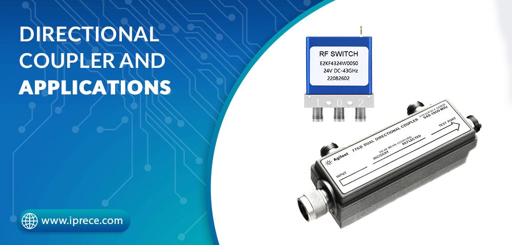
Directional couplers are electronic devices that are widely used in radio frequency (RF) systems to separate and measure the power of different signals. These couplers allow a portion of the RF power to be extracted from the transmission line without affecting the performance of the system. In this comprehensive guide, we will delve deeper into directional couplers, their functions, applications, types, and selection criteria.
What is a Directional Coupler?
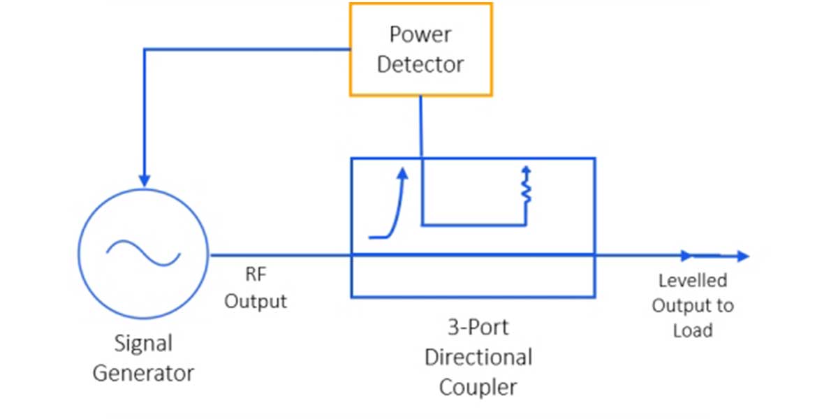
A directional coupler is an electronic device that is used to extract a portion of the RF power from a transmission line and direct it to another circuit. The coupler is designed to be a one-way device that allows energy to flow in only one direction while blocking the reverse flow of energy. This directional property makes the coupler ideal for measuring the power of different signals in RF systems.
How Does a Directional Coupler Work?
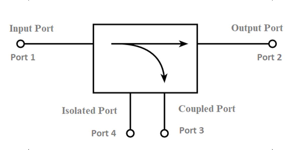
A directional coupler works on the principle of electromagnetic induction. The coupler consists of a four-port network that includes a pair of coupled transmission lines. The main transmission line is connected to the input and output ports, while the coupled transmission line is connected to the coupled port.
When RF energy is applied to the input port, a portion of the energy is coupled to the coupled port through the coupled transmission line. The amount of energy coupled to the coupled port depends on the coupling factor of the coupler. The remaining energy continues to flow through the main transmission line to the output port.
Applications of Directional Couplers
Directional couplers are used in a wide range of applications, where the separation and measurement of different signals is required. Some of the most common applications include:
RF Amplifiers: Directional couplers are used in RF amplifiers to measure the power of the input and output signals. In an RF amplifier, the input signal is amplified and then transmitted to the output port. Directional couplers are used to extract a portion of the input and output signals and measure their power levels. This allows the performance of the amplifier to be monitored and optimized.
Antennas: Directional couplers are used in antennas to measure the power of the transmitted and received signals. In an antenna system, the energy is transmitted from the transmitter to the antenna, which then radiates the energy into space. The energy reflected back from targets is received by the antenna and transmitted to the receiver. Directional couplers are used to extract a portion of the transmitted and received signals and measure their power levels. This allows the performance of the antenna system to be monitored and optimized.
Test and Measurement: Directional couplers are widely used in test and measurement applications, where the separation and measurement of different signals is required. Directional couplers are used in network analyzers, spectrum analyzers, and other test and measurement equipment to measure the power of different signals.
Types of Directional Couplers
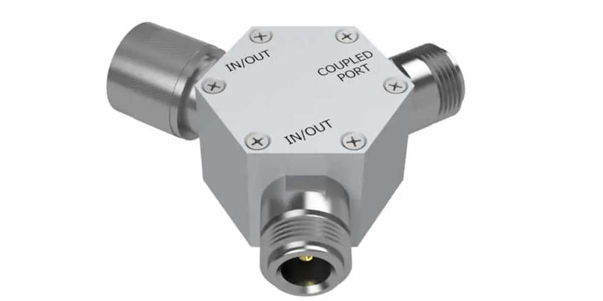
There are several types of directional couplers available in the market, including:
Resistive Coupler
A resistive coupler is a simple and inexpensive coupler that uses a resistor to couple the energy from the main transmission line to the coupled port. Resistive couplers are used in low power applications where high accuracy is not required.
Hybrid Coupler
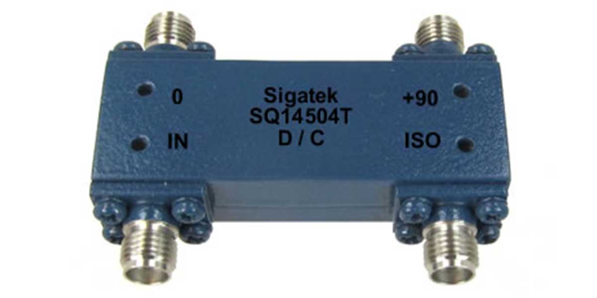
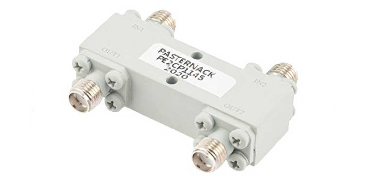
A hybrid coupler is a four-port device that uses a pair of coupled transmission lines to split the input signal into two equal output signals. The coupler is designed to have equal power division and equal phase shift between the output signals. Hybrid couplers are commonly used in power dividers and combiners.
Quadrature Coupler
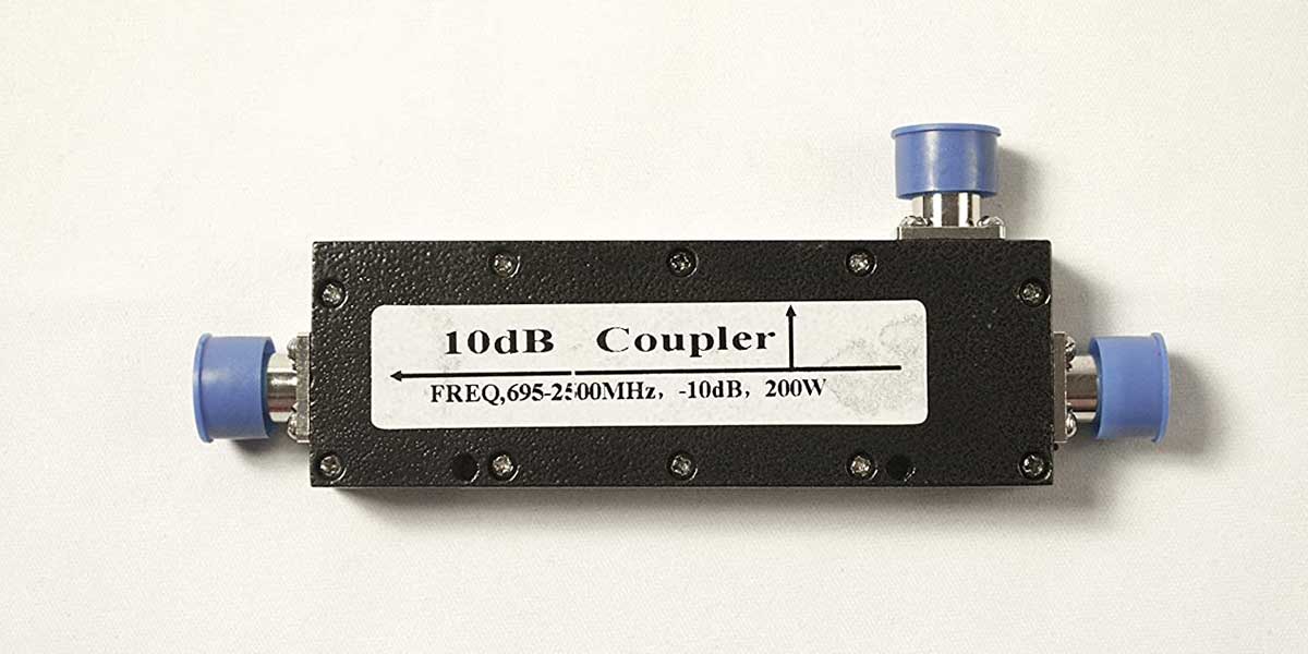
A quadrature coupler is a four-port device that provides two output signals that are 90 degrees out of phase with each other. Quadrature couplers are commonly used in phase shifters
