


Applications
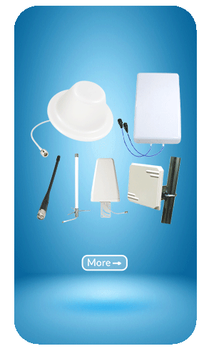
- Antennas
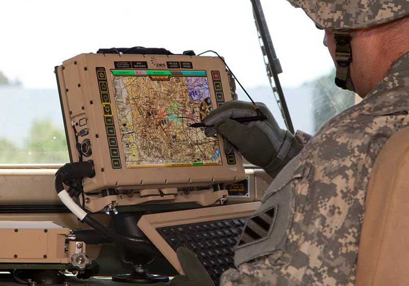
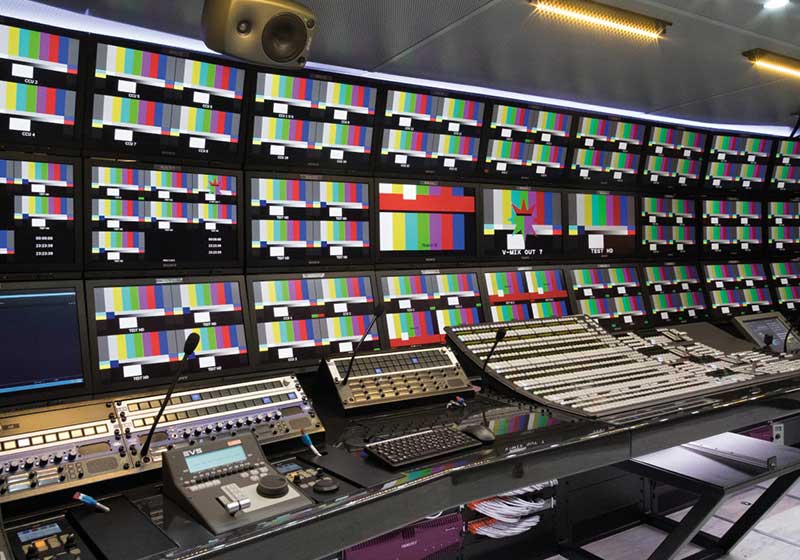
- Telecommunication
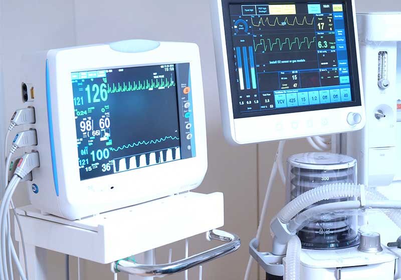
- Instrumentation
- PC – LAN
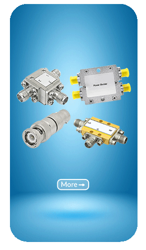
Features
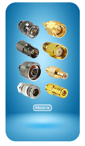
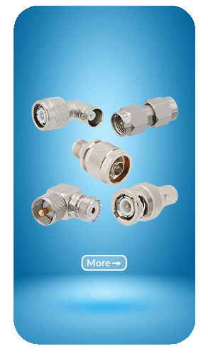
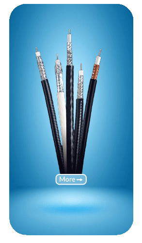
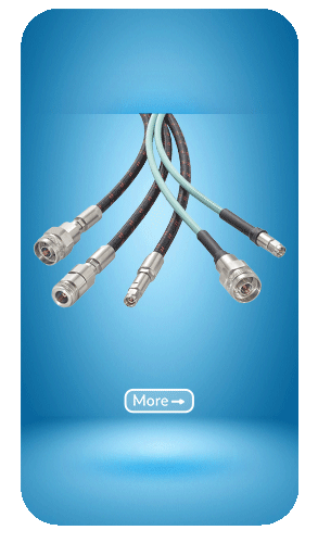
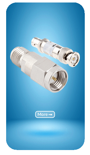
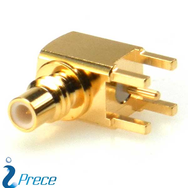
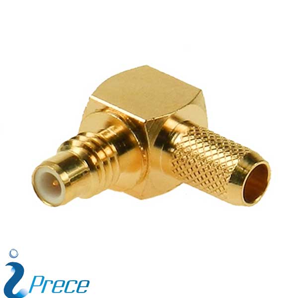
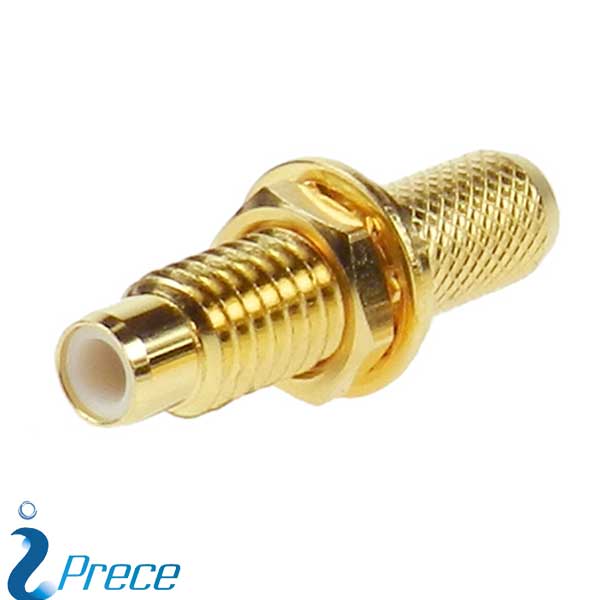
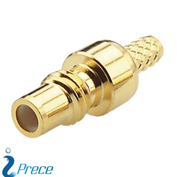
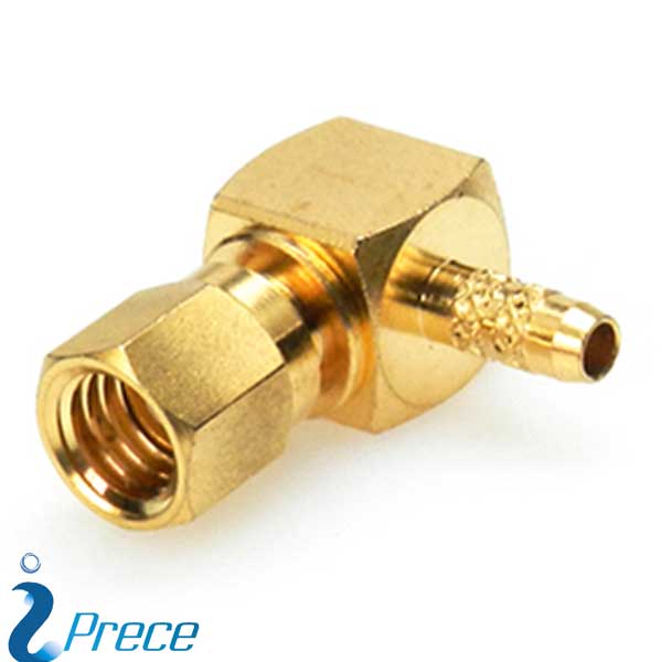
- Cable Connectors (straight and right angle) for flexible and semi-rigid cables with diameters to 3.1 mm
- Frequency range up to 10 GHz
- Screw-on coupling mating.
- 50 and 75 ohm impedance.
- Various plating options.
- Interface according to IEC 169-9, MIL-STD-348B
Special Notice
- The specification is listed below for information. All dimensions are fully compatible with Military requirements.
- Iprece provides commercial grade connectors, and environmental requirements we can test in-house.
- For electrical and mechanical test, we can support most of it in-house.
Electrical
| Impedance | 50Ω / 75Ω |
| Frequency Range | 0 to 10 GHz |
| VSWR | ≤1.3 (straight connector) ≤1.45 (right angle connector) |
| RF Leakage | ≥90 dB |
| Dielectric Withstanding Voltage | 750 V rms |
| Voltage Rating | 250 V rms (depending on cable) |
| Inner Contact Resistance | ≤5 mΩ |
| Outer Contact Resistance | ≤2.5 mΩ |
| Insulation Resistance | ≥1 GΩ |
Mechanical
| Mating | Screw-on Coupling |
| Connector Durability | ≥500 Cycles (for beryllium copper female contact only) |
| Recommended Mating Torque | 2.2 lbs ~ 3.1 lbs(max. 6.2Lbs) |
| Coupling Nut Retention Force | ≥33.72 lbs |
| Cable Retention Force | ≥ 7.3 lbs (for RG178) ≥ 12.1 lbs (for RG316) |
Environmental
| Temperature Range | -65° C to 165° C |
| Corrosion (Salt Spray) | MIL-STD-202, Method 101, Cond. B |
| Vibration | MIL-STD-202, Method 204, Cond. D |
| Thermal Shock | MIL-STD-202, Method 107, Cond. B |
| Mechanical Shock | MIL-STD-202, Method 213, Cond. C |
Material
| Parts Name | Material | Plating |
| Body | Brass | Nickel or Gold |
|
Inner Contact |
Male: Brass Female: Brass, Beryllium Copper or Phosphor Bronze |
Gold |
| Insulator | PTFE | None |
| Crimp Ferrule | Annealed Copper | Same as Body |
Note: Other Material/Finish is Available on Request.

Reviews
There are no reviews yet.