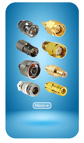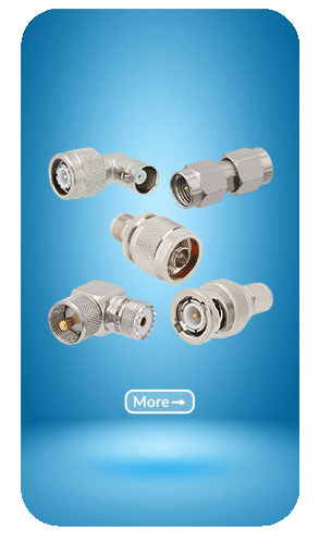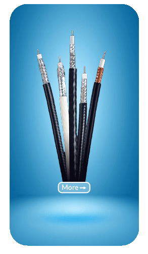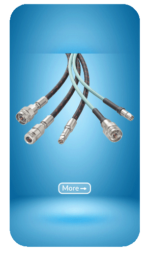
Military Standard For RF Connectors
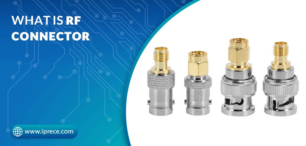
March 7, 2023A coaxial RF connector (radio frequency connector) is an electrical connector designed to work at radio frequencies in the multi-megahertz range. RF connectors are typically used with coaxial cables and are designed to maintain the coaxial design’s shielding. Better models also minimize the change in transmission line impedance at the connection. Mechanically, they provide a fastening mechanism (thread, bayonet, braces, blind mate) and springs for a low ohmic electric contact while sparing the gold surface, thus allowing very high mating cycles and reducing the insertion force.
RF connectors are designed to perform in rugged, challenging environments while maintaining low insertion losses, superb voltage standing wave ratio, and other mechanical and electrical functions. They typically offer a secure mating connection and high mating cycles with multiple fastening types available.
What is the Difference Between RF and Coaxial?
The terms RF and coaxial are often used interchangeably, but it is essential to note the distinction between them.
In simple terms, RF is the signals transferred through shielded cables, while coaxial typically refers to the cable itself. RF signals are often transmitted via coaxial cable, and it is also possible for the coaxial cable to feature RF receivers and transmitters at the ends. Coaxial cables are sometimes called RF cables, yet it is a common misconception that RF and coaxial mean the same thing.
Many RF connectors of IPRECE can be used with coaxial cable to provide highly-screened connections. This means that they are suitable for use with RF applications, specific test and measurement equipment, and environments where RF and screening applications are required.
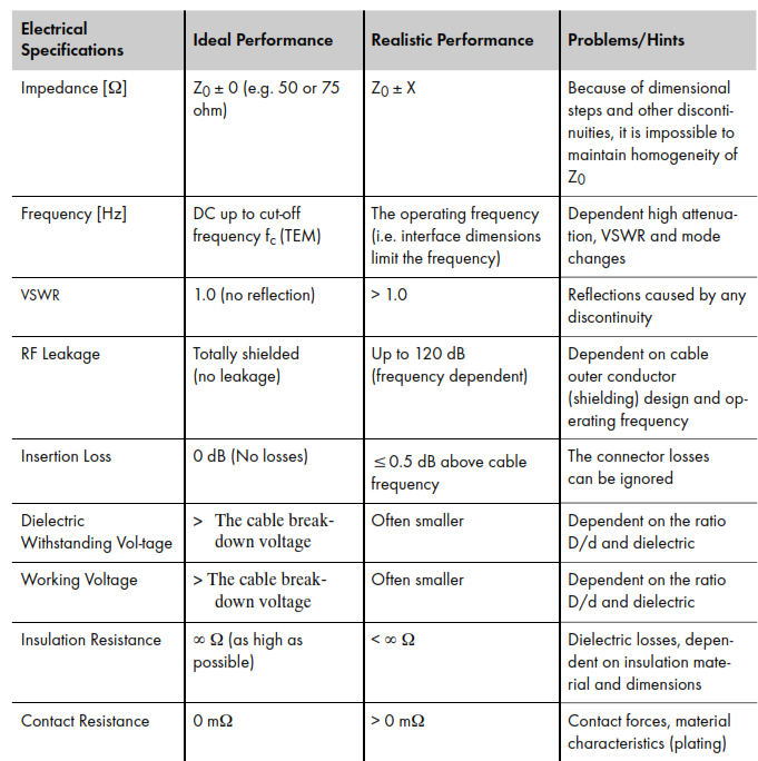
When an RF connector is designed, the main goal is to minimize any departures from the ideal line about costs, loss, reflection, and dispersion. It is called a homogeneous or ideal RF connector with optimum conditions. Usually, this perfect performance cannot be achieved by looking at just one part of the connector characteristics. The factors influencing the performance include several electricals, mechanical, environmental, material, and economic considerations.
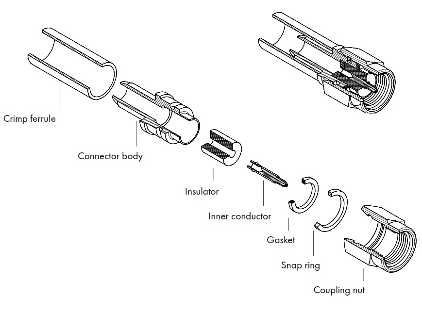
A coaxial connector consists of several components. The optimized coaxial connector will usually be built up of the elements shown below :
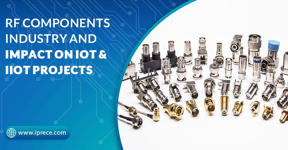
What Type of RF Connectors Does IPRECE Supply?
- 0/2.3
- 12G-SDI BNC (12GHz)
- 12G-SDI MCX (12GHz)
- 4mm
- 92mm (K)
- 6G-SDI 1.0/2.3 (6GHz)
- BNC
- DIN 7/16
- F
- FME
- MCX
- Mini UHF
- MMCX
- N
- QMA
- Reverse Polarity (RP)
- RF Switch
- RF Terminator
- RF Test Probe
- SMA
- SMB
- SMC
- SMP
- SSMA
- SSMB
- SSMC
- SMPM
- Specialty Connector
- Surge Protector
- TNC
- TS9
- UHF
- Ultra-Tiny BNC (50 ohms)
- Ultra-Tiny BNC (75 ohm) (12GHz)
- Waterproof Series
Our RF Connector Styles:
- Balun
- Crimp Type (for Flexible Cable)
- Clamp Type (for Flexible Cable)
- Clamp Type (for Low Loss Cable)
- Clamp Type (for Semi-Rigid Cable)
- Direct Solder Type (for Semi-Rigid Cable)
- SMT Type
- Switch
- PCB Mount Type
- Solder Terminal Type
- End Launch Type
- Edge Mount Type
- Panel Mount Type
- Bulkhead Receptacle, Solder Pot Terminal
- Twist-On Type (for Flexible Cable)
- RF Terminator
- Dust Cap
- RP BNC
- RP MMCX
- RP MCX
- RP N
- RP SMA
- RP TNC
- Surge Protector
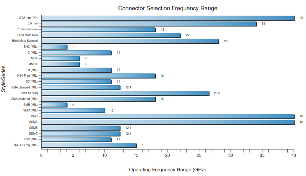
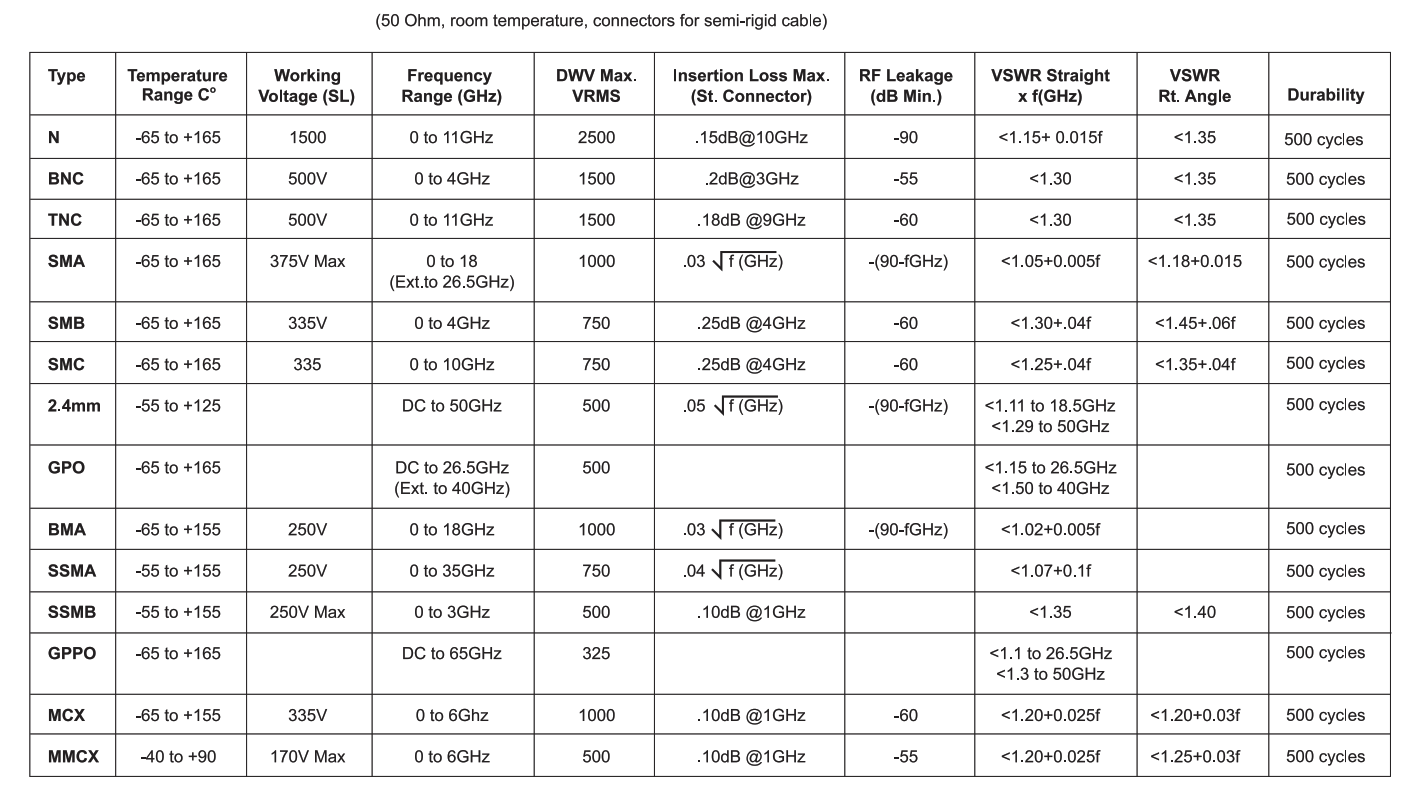
Frequency Range Chart :
Since radiofrequency radiation has both an electric and a magnetic component, it is often convenient to express the intensity of the radiation field in terms of units specific to each component. The electromagnetic spectrum holds all possible radio frequencies ranging from 3 kHz o 30 GHz. RF technology is utilized throughout telecommunications, space, aerospace, autonomous vehicles, medical and military applications. IPRECE offers a wide variety of RF components, including RF connectors, RF adapters, attenuators, coaxial cable assemblies, etc. This quick reference guide outlines the frequency range of these components.
How to Install RF Coaxial Connectors:
IPRECE RF coaxial connectors can be installed in one of two different ways.
The first installation method involves simply crimping the connector onto the cable. Alternatively, the connector can be screwed onto the end of the cable. Both installation techniques are commonly used and relatively simple to perform.
Another difference refers to the center pin. Depending on your preferred installation method, this can be soldered or crimped. Soldering the center pin is typically the standard approach, but crimping is a possible alternative.
The following steps provide a handy breakdown describing how to connect an RF adapter to coaxial cable. Remember to familiarize yourself with the manufacturer’s instructions before beginning the task.
- Decide which method of connection you want to use (crimping or soldering)
- Strip the cable back, as per the manufacturer’s guidelines
- Either crimp or solder the center pin, depending on the connection type you have chosen
- Attach the outer to complete the process
While this is not a complex process, it is still essential to perform it correctly to avoid causing damage to the components. Once you have familiarized yourself with the process and are confident to proceed, following the steps above should quickly help you complete the task.
There are also three different coupling mechanisms for installation. These are:
- Screwed Coupling – this consists of thread and coupling nut with a maximum torque setting for coupling nut captivation
- Bayonet Coupling – this type of connection is essential for sturdy mechanism and faster mounting
- Snap-On Coupling – this is a quick snap-in connection and disengagement mechanism suitable for most small connectors
Some of Most Common RF Connector Types
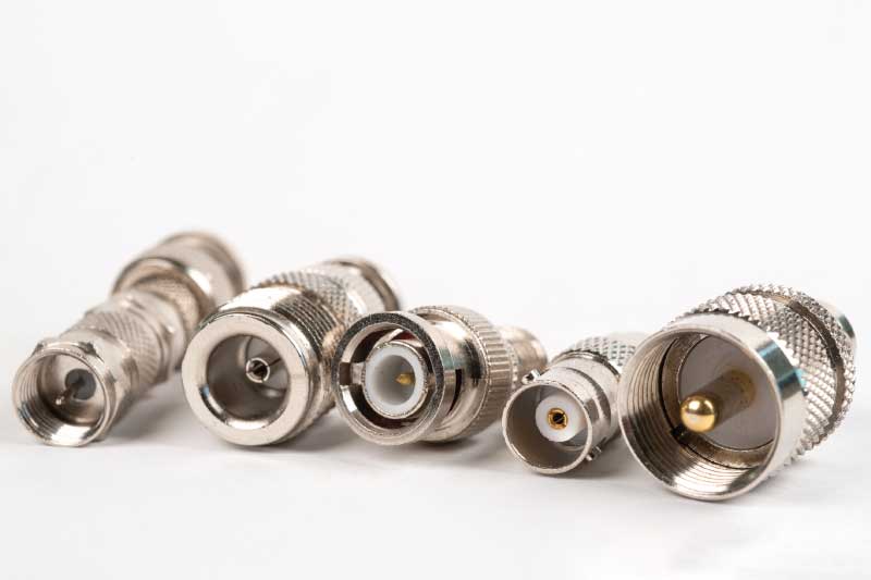
Some of the most common RF connector types include:
- Type N Connectors
- TNC Connectors
- BNC Connectors
- SMA Connectors
1. Type N Connector
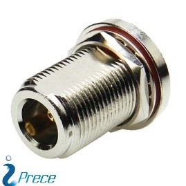
The Type N connector is a threaded, weatherproof, medium-sized connector for durable applications that can easily handle frequencies up to 11 GHz. This type of connector follows MIL-STD-348 and is widely used in lower frequency microwave systems where ruggedness and low cost are needed.
Click here to purchase recommended Type N connector
2. TNC Connector
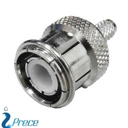
TNC is a threaded version of the BNC connector and has a better performance than the BNC connector at microwave frequencies. It is used in radio and wired applications.
Click here to purchase recommended TNC connector
3. BNC Connector
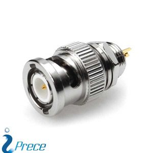
BNC is a miniature quick connect/disconnect RF connector commonly used for low-frequency applications. It is used initially for the military sector and has gained wide acceptance in a composite video on commercially used video devices and RF applications up to 2 GHz.
Click here to purchase recommended BNC connector
4. SMA Connector
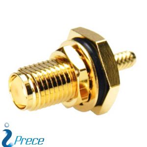
SMA or SubMiniature version A connectors are semi-precision coaxial RF connectors operating up to 18 GHz, though some proprietary versions are rated to 26.5 GHz. It is commonly used in RF power amplifiers, RF isolators, microwave systems, mobile telephone antennas, WiFi antenna systems, and radio astronomy at 5 GHz.
Click here to purchase recommended SMA connector
For more information, you can follow our page IPRECE and recommend us to your friends…


