Engineered for 60GHz: inside our low loss flexible coaxial cable
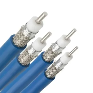
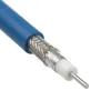
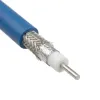
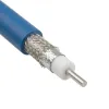
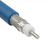
The LFX Series low loss flexible RF cables combine low signal attenuation with high mechanical flexibility. The internal design features a silver-plated copper center conductor and a microporous PTFE dielectric.
This material combination delivers 76% to 77% propagation velocity. Controlled capacitance ranges from 86.8 to 87.7 pF/m.
To block electromagnetic interference, LFX low loss flexible cables utilize a robust dual-shield construction. This includes an aluminum tape inner shield and a silver-plated copper outer braid.
This shielding structure delivers a minimum efficiency of 90 dB. Additionally, an outer FEP jacket ensures reliable performance from -55 to +125°C.
LFX series material specifications
Parameter | LFX-280 | LFX-350 | LFX-500 | LFX-750 | Material |
Center Conductor (mm) | 0.56 | 0.92 | 1.45 | 2.31 | Silver Plated Copper |
Dielectric (mm) | 1.60 | 2.70 | 4.25 | 6.60 | Microporous PTFE |
Inner Shield (mm) | 1.70 | 2.80 | 4.35 | 6.70 | Aluminum Foil |
Outer Braid (mm) | 2.05 | 3.23 | 4.85 | 7.20 | Silver Plated Copper Braid |
Jacket (mm) | 2.60 | 3.50 | 5.20 | 7.80 | FEP |
LFX coax cables electrical specifications
Parameter | LFX-280 | LFX-350 | LFX-500 | LFX-750 |
Impedance | 50 Ω | 50 Ω | 50 Ω | 50 Ω |
Cut-off Frequency | 60 GHz | 40 GHz | 28 GHz | 20 GHz |
Velocity of Propagation (Vp) | 76% | 76% | 77% | 76% |
Shielding Efficiency | >90 dB | >90 dB | >90 dB | >90 dB |
Capacitance | 87.7 pF/m | 87.7 pF/m | 86.8 pF/m | 87.7 pF/m |
Delay | 4.39 nS/m | 4.39 nS/m | 4.32 nS/m | 4.39 nS/m |
Voltage Withstand (DC) | 500 | 800 | 1500 | 2000 |
Peak Power | 0.8 kW | 1.8 kW | 5 kW | 8 kW |
LFX series mechanical & environmental specifications
Parameter | LFX-280 | LFX-350 | LFX-500 | LFX-750 |
Bend Radius (Installation) | 15 mm | 16 mm | 20 mm | 33 mm |
Bend Radius (Repeated) | 30 mm | 35 mm | 52 mm | 78 mm |
Weight | 17.5 g/m | 28 g/m | 59 g/m | 105 g/m |
Operating Temperature | -55 to +125°C | -55 to +125°C | -55 to +125°C | -55 to +125°C |
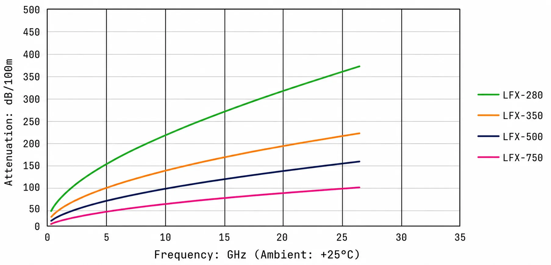
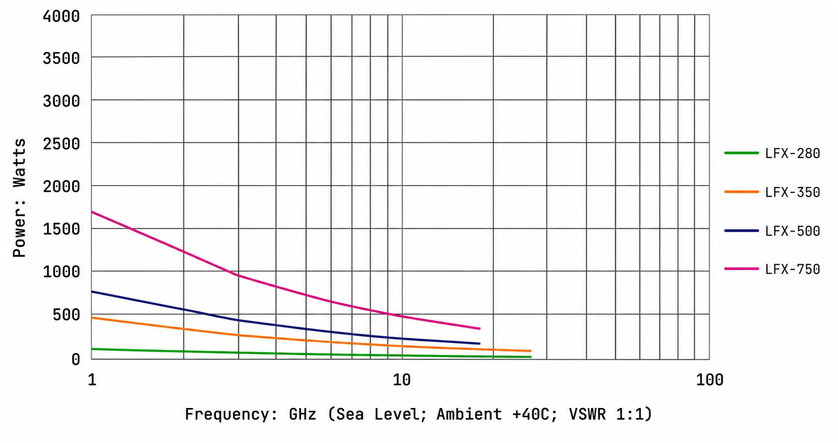
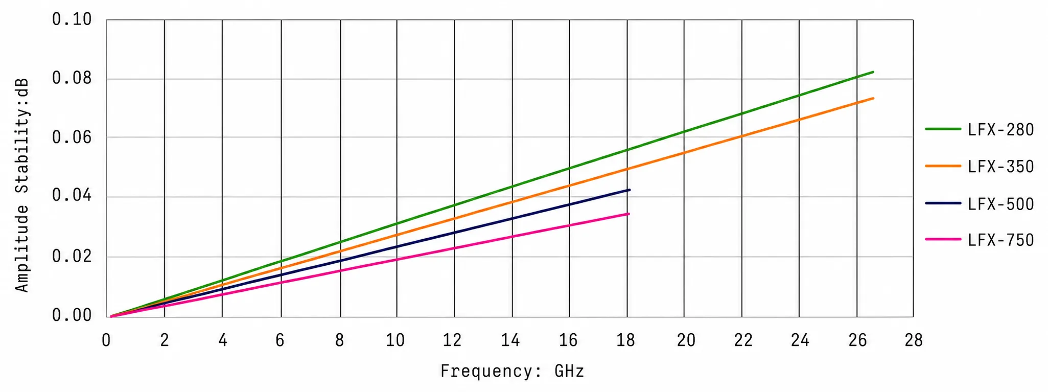
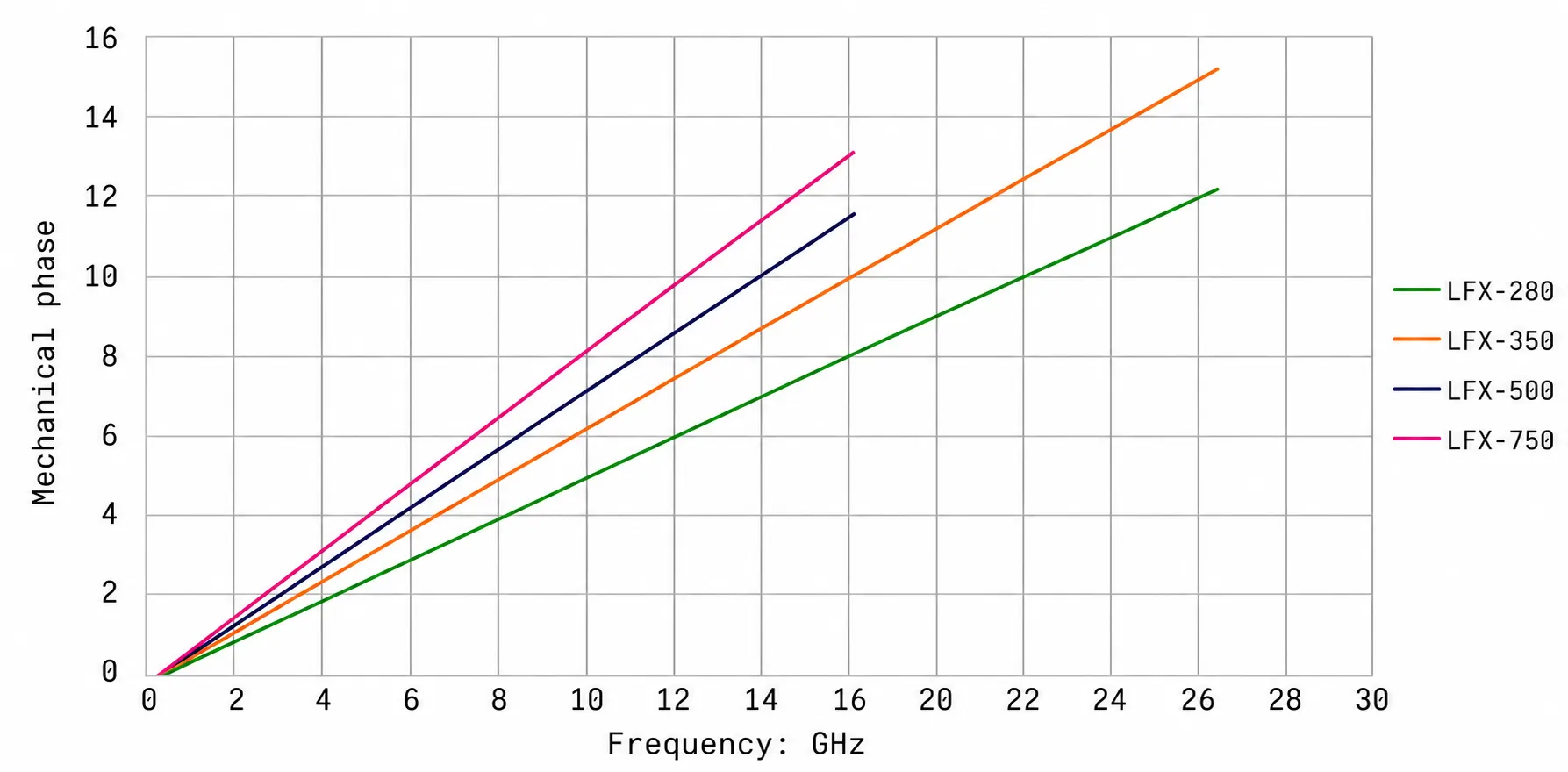
LFX series performance curves
Review the empirical performance charts for LFX low loss flexible rf cable series across frequency and temperature ranges.