
What is an RF Connector?
An RF connector (Radio Frequency connector) is an electromechanical device designed to join coaxial cables or connect them to printed circuit boards (PCBs) and equipment, maintaining the shielding and specific impedance of the transmission line to minimize signal reflection and power loss.
Precision Engineered RF Interconnects
As an ISO 9001:2015 certified manufacturer, iPrece supplies coaxial RF connectors engineered to strict industry tolerances. By utilizing precision machining and controlled plating processes, we achieve the exact mechanical specifications required for stable electrical performance and extended mating cycles.
To eliminate performance uncertainty, every high-frequency component undergoes 100% VNA RF testing. This strict quality assurance protocol provides your QA and procurement teams with direct access to verifiable test data and compliance certificates, ensuring complete confidence in your supply chain.
RF Connector Types & Interfaces Available at iPrece
1.85mm (Ultra-Precision): Delivers mode-free performance up to 67 GHz. Built for advanced test systems.
2.92mm (Precision): Operates reliably up to 40 GHz. Features a ruggedized air dielectric.
SMP: Provides a space-saving push-on design. Supports frequency ranges up to 40 GHz.
4.3-10 (Low PIM): Achieves PIM levels better than -166 dBc. Engineered for 5G telecom infrastructure.
SMA: Operates up to 18 GHz (standard) or 26.5 GHz (precision). Uses a secure threaded coupling.
N-Type: Handles medium power levels up to 11 GHz. Includes an internal gasket for weatherproofing.
TNC: Maintains stable connectivity in high-vibration settings. Functions up to 11 GHz.
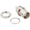
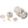
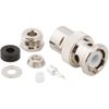
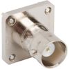
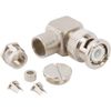
BNC: Enables rapid connection via a two-stud bayonet lock. Optimized for 4 GHz lab environments.
MCX: Reduces footprint by 30% compared to SMB RF Connector types. Operates efficiently up to 6 GHz.
SMB: Offers quick connect and disconnect snap-on mating. Rated for 4 GHz operations.
1.0/2.3: Allows dense packaging in telecom panels. Operates effectively at 50 Ω or 75 Ω.
F-Type: Provides cost-effective 75 Ω impedance. Designed for CATV routing up to 3 GHz.
Essential Parameters for Coaxial Connector Selection
Engineers must evaluate specific data points before specifying a RF coaxial connector.
Impedance: Match the connector to your system requirement. Select 50 Ω for data transmission or 75 Ω for video routing.
Maximum Frequency: Ensure the coax connector operates below its cutoff frequency. This prevents higher-order mode generation.
VSWR (Voltage Standing Wave Ratio): Specify low VSWR values. Low numbers indicate efficient power transfer and minimal signal reflection.
Passive Intermodulation (PIM): Require low-PIM interfaces like 4.3-10 for multi-carrier cellular networks.
Mating Cycles: Check the mechanical durability rating. Precision lab connectors demand higher cycle capacities than standard commercial types.
RF Connector Uses Across Key Industries
Engineers specify our coaxial connectors for critical infrastructure requiring stable RF transmission. The specific coaxial RF connector uses vary based on system frequency, power levels, and environmental conditions.
5G & Telecommunications: Modern cellular networks demand strict low-PIM performance. Engineers use 4.3-10 and N-Type interfaces for macro-cell antennas, Distributed Antenna Systems (DAS), and microwave backhaul links to maximize network capacity.
Aerospace & Defense: Military systems operate in extreme environments. TNC and SMA connectors provide secure RF routing for phased-array radars, satellite communications (SATCOM), and electronic warfare modules requiring MIL-STD compliance.
Test & Measurement: Laboratory equipment requires absolute precision and repeatability. Test engineers utilize our 1.85mm and 2.92mm coaxial connectors for VNA test ports, high-frequency oscilloscopes, and precise RF calibration kits operating up to 67 GHz.
High-Density PCB & Embedded Systems: Space constraints demand reliable miniaturization. SMP and MCX connectors enable secure board-to-board and blind-mate RF interconnects within compact RF modules and transceiver designs.
Broadcast & Video Routing: High-definition signal transmission requires strict 75 Ω impedance. Broadcast engineers deploy standard BNC, 1.0/2.3, and F-Type connectors for studio video routers and broadband CATV distribution networks.
Coaxial RF Connector FAQs
What is the functional difference between threaded and push-on RF connectors?
Threaded connectors like SMA provide high mechanical stability and maximum RF shielding. Push-on types like SMP enable fast mating and support dense board-to-board layouts.Why is Low PIM a requirement for modern cellular networks?
High PIM causes signal distortion and reduces overall network capacity. Low-PIM connectors like the 4.3-10 series prevent interference between transmitted and received signals in 5G systems.Can I mate a 2.92mm male RF connector with an SMA female RF connector?
Yes. The 2.92mm and SMA interfaces are mechanically compatible. However, mating them degrades the precision of the 2.92mm component and limits the maximum frequency to 18 GHz.How do you verify the performance of your millimeter-wave connectors?
We perform 100% VNA testing on all high-frequency coaxial RF connectors. We provide exact S-parameter data and detailed test reports to simplify your quality validation process.