

Ultra-low-loss architecture: inside LMR RF cable
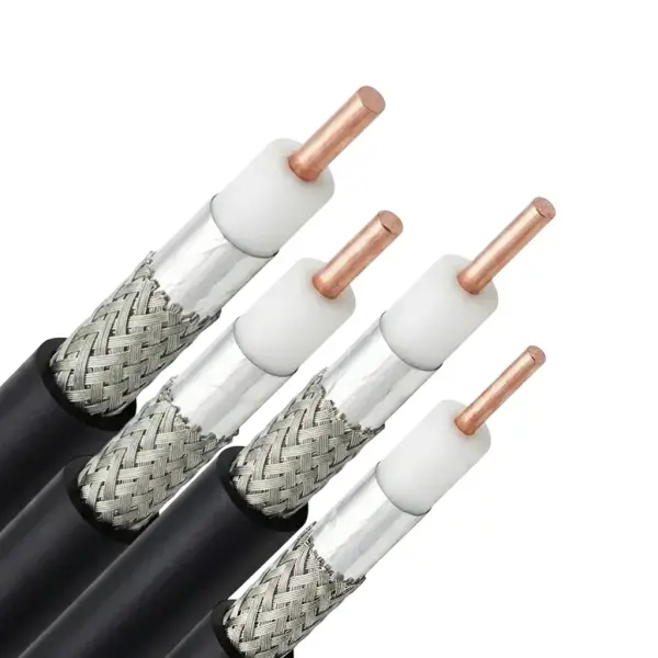
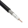
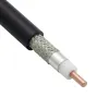
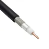
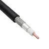
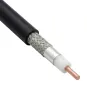
The LMR coax cable family offers a multi-layer architecture optimized for flexible, harsh-environment routing. Cross-sections range from ultra-compact LMR-100 (0.110" OD) to heavy-duty LMR-1200 (1.200" OD).
The core features a solid or stranded center conductor insulated by a closed-cell foam PE or low-density PTFE dielectric. Dual-layer shielding—an overlapped aluminum tape covered by a tinned copper braid—ensures complete mechanical integrity and pull retention. Outer jacket options include UV-resistant PE, fire-retardant (FRPE), direct burial (DB), and PVDF for plenum spaces.
Electrically, LMR coaxial cables deliver exceptionally low signal attenuation and >90 dB RF shielding effectiveness across all variants. Operating stably up to 8 GHz, these transmission lines maintain excellent VSWR and velocity of propagation (VoP) values from 66% to 88%. Peak power handling scales from 0.6 kW for ultra-compact profiles up to 90 kW for heavy-duty base station feeder lines.
LMR coaxial cable specifications
The following tables detail the exact material parameters, electrical performance, and mechanical limits across four primary LMR RF cable series (Standard, UltraFlex, LLPX, and 75-Ohm).
LMR cables material specifications
Specification Parameter | LMR Standard Series | LMR UltraFlex Series | LMR LLPX Series | LMR 75 Ohm Series |
Center Conductor Core | Solid BC, Stranded BC, Solid BCCAI, or BC Tube | Stranded BC | Solid Bare Copper | Solid Bare Copper |
Primary Dielectric Layer | Solid / Foam PE | Foam PE | ePTFE (Low-density PTFE) | Foam PE |
Internal Shielding Tape | Aluminum Tape | Aluminum Tape | Aluminum Tape | Aluminum Tape |
External Shielding Braid | Tinned Copper | Tinned Copper | Tinned Copper | Tinned Copper |
Outer Protective Jacket | PE, FRPE, FRPVC, PVC | TPE, FRPE | PVDF Fluoropolymer | PE, FRPE |
LMR RF cables electrical specifications
Specification Parameter | LMR Standard Series | LMR UltraFlex Series | LMR LLPX Series | LMR 75 Ohm Series |
Nominal Impedance | 50 Ω | 50 Ω | 50 Ω | 75 Ω |
Max Operational Frequency | 5.2 GHz to 8 GHz | 6 GHz | 6 GHz to 8 GHz | 6 GHz |
Velocity of Propagation (VoP) | 66% to 88% | 74% to 87% | 76% | 84% to 87% |
RF Shielding Effectiveness | >90 dB | >90 dB | >90 dB | >90 dB |
DC Voltage Withstand | 500 to 6000 Volts DC | 1000 to 4000 Volts DC | 1000 to 6000 Volts DC | 1500 to 4000 Volts DC |
Peak Operational RF Power | 0.6 kW to 90 kW | 2.5 kW to 40 kW | 2.5 kW to 90 kW | 5.6 kW to 40 kW |
LMR coax cables mechanical & environmental specifications
Specification Parameter | LMR Standard Series | LMR UltraFlex Series | LMR LLPX Series | LMR 75 Ohm Series |
Operating Temperature | -40 °C to +85 °C | -40 °C to +85 °C | -40 °C to +125 °C | -40 °C to +85 °C |
Outer Diameter Range | 2.79 mm to 30.48 mm | 4.95 mm to 14.99 mm | 4.45 mm to 26.67 mm | 6.10 mm to 14.99 mm |
Min Bend Radius (Installation) | 6.35 mm to 165.10 mm | 12.70 mm to 38.10 mm | 12.70 mm to 152.40 mm | 19.05 mm to 38.10 mm |
Min Bend Radius (Repeated) | 25.40 mm to 304.80 mm | 50.80 mm to 152.40 mm | 50.80 mm to 304.80 mm | 63.50 mm to 152.40 mm |
Tensile Strength | 66.7 N to 5782.7 N | 177.9 N to 1556.9 N | 177.9 N to 4337.0 N | 355.9 N to 1556.9 N |
Flat Plate Crush Resistance | 1.75 N/mm to 43.78 N/mm | 1.75 N/mm to 7.01 N/mm | 1.75 N/mm to 65.67 N/mm | 3.50 N/mm to 10.51 N/mm |