RG Coaxial Cable Series

RG coaxial cable series are flexible and semi-rigid transmission lines for RF applications. These cables support frequencies up to 40 GHz with exact 50 and 75 Ω impedances. Single to triple shielding layers maintain signal isolation across telecommunication systems.

Impedance50 Ω / 75 Ω Ω
Max frequencyUp to 40 GHz
Outer diameter2.54 to 10.29 mm
ShieldingUp to 110 dB
  • Up to 40 GHz operating frequency
  • PTFE, PE, PE (F), and FEP dielectrics
  • Thermal ratings up to 200°C
  • Flexible and semi-rigid configurations
Fast Production🏭 OEM Direct🛡️ 100% VNA Tested
15 Products Found
Part / Descriptionoperating-temp-minoperating-temp-maximpedancecapacitance-pf-m-center-conductor-diameter-mm-center-conductor-materialActions
-40 C80 C7567.261.22Tinned Copper
Details
-55 C200 C50316.440.94Silver Plated Copper Clad Steel
Details
-40 C80 C50101.970.48Copper Clad Steel
Details
-55 C200 C7563.65
Details
-25 C70 C50101.052.29Copper
Details
-20 C80 C50101.05Silver Plated Copper
Details
-55 C200 C50104.990.51Silver Plated Copper Clad Steel
Details
-55 C200 C5096.462.39Silver Plated Copper
Details
-55 C200 C50104.99Silver Plated Copper
Details
-55 C125 C5095.910.91Silver Plated Copper Clad Steel
Details

Target Applications & Industries

ATE Systems

Aerospace & Defense

Telecom Base Stations

Medical Instrumentation

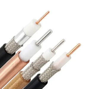
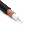
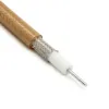
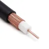
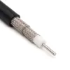
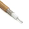
RG cables structural design and signal integrity

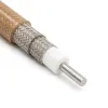
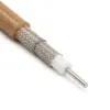
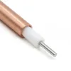
The RG coaxial cable series minimizes insertion loss across long transmission lines. Solid center conductors provide phase stability for test instruments. Stranded configurations ensure mechanical flexibility for dynamic routing requirements.

Core dielectrics include PE, foam PE (F), and solid PTFE. These materials establish signal propagation velocities between 65.9% and 85%. This architecture controls signal delay and reduces internal power dissipation.

Coaxial RG cables utilize outer shields ranging from single copper to triple-shielded matrices. Multiple conductive layers prevent electromagnetic interference in dense server racks. This maintains signal isolation across sensitive aerospace and military enclosures. These shielding structures ensure strict MIL-STD compliance for defense systems.

Outer jackets feature standard PVC, PVC (NC), and FEP. Non-contaminating PVC (NC) jackets prevent plasticizer migration into the dielectric core. This chemical stability extends the physical lifespan of the cable.

PTFE cores and extruded FEP jackets support high-temperature environments. These RG cables operate continuously up to 200 °C. Jacket diameters range from 2.54 mm to 10.29 mm.

RG coaxial cable specifications

Compare RG cable types specifications across three tables: electrical, mechanical, and material & environmental.

RG RF cables electrical specifications

Generic Family

Impedance

VoP

Attenuation @ 1 GHz

Max Power @ 1 GHz

Max Frequency

No. of Shields

RG402

50 Ω

69.5 %

36.42 dB/100 m

450 W

34 GHz

1

RG405 Tinned

50 Ω

N/A

72.18 dB/100 m

N/A

40 GHz

1

RG58

50 Ω

65.9 %

65.62 dB/100 m

44 W

5 GHz

1

RG8

50 Ω

66.0 %

26.25 dB/100 m

190 W

1 GHz

1

RG59

75 Ω

66.0 %

37.73 dB/100 m

77 W

1 GHz

1

RG6-CATV

75 Ω

85.0 %

21.49 dB/100 m

6.5 W

3 GHz

3

RG142

50 Ω

70.0 %

42.32 dB/100 m

N/A

8 GHz

2

RG316

50 Ω

69.0 %

124.67 dB/100 m

N/A

3 GHz

1

RG393

50 Ω

69.5 %

24.61 dB/100 m

1700 W

10 GHz

2

RG400

50 Ω

70.0 %

48.23 dB/100 m

600 W

12.4 GHz

2

RG coax cables mechanical specifications

Generic Family

Flex Type

Center Conductor

Strands

Min Bend Radius (One Time)

Min Bend Radius (Repeated)

Jacket Diameter

RG402

Semi-Rigid

Solid

1

N/A

6.35 mm

N/A

RG405 Tinned

Semi-Rigid

Solid

1

1.27 mm

N/A

N/A

RG58

Flexible

Stranded

19

24.89 mm

49.78 mm

4.95 mm

RG8

Flexible

Stranded

7

N/A

N/A

10.29 mm

RG59

Flexible

Solid

1

N/A

N/A

6.15 mm

RG6-CATV

Flexible

Solid

1

N/A

35.05 mm

7.06 mm

RG142

Flexible

Solid

1

N/A

25.40 mm

4.95 mm

RG316

Flexible

Stranded

7

N/A

N/A

2.59 mm

RG393

Flexible

Stranded

7

N/A

99.06 mm

9.91 mm

RG400

Flexible

Stranded

19

N/A

25.40 mm

4.95 mm

Coaxial RG cables material & environmental specifications

Generic Family

Dielectric Material

Outer Jacket Material

Max Operating Temp

Coax Type

RG402

PTFE

Copper (No Jacket)

125 °C

Coax

RG405 Tinned

PTFE

Tinned Copper (No Jacket)

125 °C

Coax

RG58

PE

PVC (NC)

80 °C

Coax

RG8

PE

PVC (NC)

80 °C

Coax

RG59

PE

PVC (NC)

70 °C

Coax

RG6-CATV

PE (F)

PVC (NC)

80 °C

Coax

RG142

PTFE

FEP

200 °C

Coax

RG316

PTFE

FEP

200 °C

Coax

RG393

PTFE

FEP

200 °C

Coax

RG400

PTFE

FEP

200 °C

Coax

RG Coaxial Cable FAQs

How does exceeding the minimum bend radius alter electrical performance in RG402 and RG405 cables?
Exceeding bend limits (6.35 mm for RG402, 1.27 mm for RG405) deforms the PTFE core. This alters concentricity between the inner conductor and outer shield. The characteristic impedance shifts away from 50 Ω. This creates localized reflections, sharp VSWR spikes, and permanent insertion loss up to 40 GHz.
What architectural differences change the velocity of propagation between standard RG58 and RG6-CATV?
Standard RG58 uses a solid PE core. It yields 65.9 % propagation velocity and 65.62 dB/100 m attenuation at 1 GHz. Conversely, RG6-CATV integrates a foam PE (F) dielectric. This cellular structure increases velocity to 85 % and minimizes dissipation losses. With triple-shielding, attenuation drops to 21.49 dB/100 m at 1 GHz.
Which RG coaxial cable series configurations perform reliably in high-temperature environments?
Standard PE dielectrics soften and fail above 80 °C. High-temperature environments require variants like RG142, RG179, RG316, RG393, and RG400. These configurations feature solid PTFE core dielectrics and extruded FEP outer jackets. This material combination maintains mechanical and phase stability up to 200 °C.
When is it necessary to specify double-shielded configurations instead of single-shielded variants?
Single-shielded RG coax cables typically provide 40 dB to 60 dB of RF isolation. High-interference environments demand greater electromagnetic interference protection. Double-shielded configurations utilize two overlapping outer conductive layers. This dual-layer structure increases overall shielding effectiveness to approximately 90 dB. Consequently, this prevents signal leakage within densely packed equipment racks.
How does center conductor construction dictate the mechanical flexibility of RG series cables?
Solid center conductors deliver lower insertion loss and higher phase stability. However, they are susceptible to metal fatigue during repeated bending. Conversely, stranded inner conductors utilize multiple fine wires twisted together. Configurations like the 19-strand RG400 or 7-strand RG316 withstand continuous dynamic flexing. This stranded design ensures mechanical reliability in high-vibration environments.
What are the electrical consequences of terminating 75 Ω cables with standard 50 Ω connectors?
Terminating 75 Ω rg coaxial cables such as RG59 or RG6-CATV with standard 50 Ω interfaces creates an impedance mismatch. This physical discontinuity reflects a portion of the RF signal back toward the source, increasing the VSWR at the connection point. For precision systems, this resulting reflection degrades overall power transmission efficiency.