
RF BNC connectors engineering overview
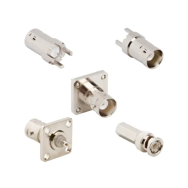
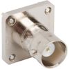
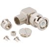
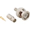
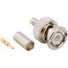
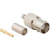
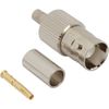
BNC connectors feature a precision bayonet-coupling interface that enables rapid, tool-free mating in high-frequency environments. This design ensures secure locking and reliable retention during frequent connection cycles, satisfying the critical requirements of laboratory testing and live broadcast equipment. Furthermore, consistent physical contact maintains low-reflection performance across demanding RF pathways.
The BNC coax connector family accommodates both 50 Ω and 75 Ω systems, with standard configurations operating efficiently up to 4 GHz. Extended-range variants support 12G-SDI video transmission up to 12 GHz when integrated with broadcast-grade coaxial assemblies. To ensure absolute signal clarity, the gold-plated center contact limits resistance to 1.5 mΩ Max, directly minimizing insertion loss for high-bandwidth data links.
BNC coax connector specifications
Review the electrical, mechanical, material, and environmental specifications for the RF BNC connector series.
BNC RF connector electrical specifications
Parameter | 50 Ω Configuration | 75 Ω Configuration |
Impedance | 50 Ω | 75 Ω |
Frequency Range | DC to 4 GHz (DC to 12 GHz Extended) | DC to 4 GHz (DC to 12 GHz Extended) |
Voltage Rating | 500 VRMS Max Continuous | 500 VRMS Max Continuous |
Dielectric Withstanding | 1500 VRMS Min | 1500 VRMS Min |
VSWR (DC to 4 GHz) | 1.3 (-18 dB) Max | 1.5 (-14 dB) Max |
VSWR (12G: DC to 6 GHz) | Not Rated / Varies by Part | 1.22 (-20 dB) Max |
VSWR (12G: 6 to 12 GHz) | Not Rated / Varies by Part | 1.43 (-15 dB) Max |
Insulation Resistance | 5000 MΩ Min | 5000 MΩ Min |
Center Contact Resistance | 1.5 mΩ Max | 1.5 mΩ Max |
Outer Contact Resistance | 0.2 mΩ Max | 0.2 mΩ Max |
RF Leakage | 55 dB Max @ 3 GHz | 55 dB Max @ 3 GHz |
Insertion Loss | 0.2 dB Max @ 3 GHz | 0.2 dB Max @ 3 GHz |
Power Handling | 316 W Max @ 1 GHz @ 25 °C | 316 W Max @ 1 GHz @ 25 °C |
BNC coaxial connector mechanical specifications
Parameter | Value / Specification |
Mating Cycles | 500 Min |
Coupling Mechanism | Bayonet |
Interface Specification | MIL-STD-348 |
Coupling Torque | Refer to MIL-STD-348 |
Mating / Unmating Force | Refer to MIL-STD-348 |
Cable Retention Force | Varies by cable and termination style |
RF BNC connector material specifications
Component | Material / Plating Specification |
Center Contact Plating | Gold, Silver, Nickel (Varies by Part) |
Body Material | Brass, Zinc Diecast, Beryllium Copper, Stainless Steel |
Body Plating | Nickel, Silver, Gold, White Bronze, Black, Tin |
Insulator Material | PTFE |
Gasket / O-Ring Material | Varies by specific part number |
BNC connector environmental specs & compliance
Parameter | Standard / Condition |
Operating Temperature | -65 °C to +165 °C |
Thermal Shock | MIL-STD-202, Method 107 (Cond. G), except +200 °C test |
Corrosion | MIL-STD-202, Method 101 (Cond. B) - 5% Salt Solution |
Vibration | MIL-STD-202, Method 204 (Cond. D) |
Mechanical Shock | MIL-STD-202, Method 213 (Cond. G) - No Discontinuity |
Moisture Resistance | MIL-STD-202, Method 106 |
Altitude | MIL-STD-202, Method 105 (Cond. C) |
RoHS Compliance | Refer to specific part number documentation |