DIN 1.0-2.3 Connector

The DIN 1.0 2.3 connector series provides RF signal transmission with a push-pull locking mechanism. Designed for space-constrained backplanes, they offer stable performance up to 10 GHz (50 Ω) and 4 GHz (75 Ω).

Coupling MechanismPush-Pull
Mating Cycles (Min)500
Max frequency10 GHz / 4 GHz
Impedance50 / 75 Ω
  • High-density PCB/panel layouts
  • Tool-less push-pull engagement
  • Brass or stainless steel
  • DIN & NFC compliant
Fast Production🏭 OEM Direct🛡️ 100% VNA Tested
78 Products Found
Part / Descriptionfrequency-maxbody-materialcontact-finishoperating-temp-minoperating-temp-maxportsActions
10 GHzBrassGold-40 °C C155 °C C1 (Single Port)
Details
10 GHzBrassGold-40 °C C155 °C C1 (Single Port)
Details
10 GHzBrassGold-40 °C C155 °C C1 (Single Port)
Details
10 GHzBrassGold-40 °C C155 °C C1 (Single Port)
Details
10 GHzBrassGold-40 °C C155 °C C1 (Single Port)
Details
10 GHzBrassGold-40 °C C155 °C C1 (Single Port)
Details
10 GHzBrassGold-40 °C C155 °C C1 (Single Port)
Details
6 GHzBrassGold-40 °C C155 °C C1 (Single Port)
Details
10 GHzBrassGold-40 °C C155 °C C1 (Single Port)
Details
10 GHzBrassGold-40 °C C155 °C C1 (Single Port)
Details

Target Applications & Industries

Broadcast video systems

Telecommunications infrastructure

Test and measurement equipment

High-density backplanes and enclosures

Data and control systems

1.0 2.3 DIN connectors: technical architecture

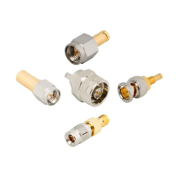
The DIN 1.0 2.3 connector architecture supports modular telecom and broadcast equipment. The push-pull coupling mechanism eliminates the radial clearance required for standard wrenches. This design allows hardware engineers to reduce center-to-center mounting pitch on PCBs. The connectors maintain high mating retention and RF shielding effectiveness (-90 dB Min DC to 1 GHz).

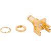
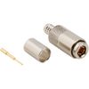
1.0 2.3 coaxial connector bodies are constructed from precision-machined brass or stainless steel. Plating options include gold, nickel, and passivation. The internal structure uses PTFE insulators and gold-plated contacts. This precise geometry yields a center contact resistance of 6 mΩ, maintaining a Return Loss of VSWR ≤ 1.05 up to 1 GHz.

1.0 2.3 RF connector specifications

Evaluate the technical parameters, material properties, and environmental compliance of DIN 1.0 2.3 connectors.

1.0 2.3 coaxial connector electrical specifications

Parameter

Specification

Impedance

50 Ω / 75 Ω

Frequency Range (50 Ω)

DC to 10 GHz

Frequency Range (75 Ω)

DC to 3 GHz (0 to 12 GHz on Extended Range Designs)

Voltage Rating

250 VRMS Max Continuous

Dielectric Withstanding Voltage

750 VRMS Max

VSWR (50 Ω, DC to 1 GHz)

1.05 (-32 dB) Max

VSWR (50 Ω, 1 to 4 GHz)

1.15 (-23 dB) Max

VSWR (50 Ω, 4 to 10 GHz)

1.38 (-16 dB) Max

VSWR (75 Ω, DC to 2 GHz)

1.22 (-20 dB) Typ.

Insulation Resistance

10000 MΩ Min

Center Contact Resistance

6 mΩ Min

Outer Contact Resistance

3 mΩ Min

RF Leakage

-90 dB Min (DC to 1 GHz)

Insertion Loss

0.1 * √f(GHz) dB Max

Power Handling

133 W @ 1 GHz @ 25 °C

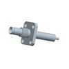
DIN 1.0 2.3 connector mechanical specifications

Parameter

Specification

Coupling Mechanism

Push-Pull

Mating Cycles

500 Min

Interface Specification

DIN 41626, 47297, NFC 93-571

Panel Mounting Features

Bulkhead Rear Mount, 2-Hole Flange, 4-Hole Flange, Thread-in, Press-Fit

1.0 2.3 DIN connector material specifications

Parameter

Specification

Body Material

Brass / Stainless Steel

Body Plating / Finish

Gold / Nickel / Passivated

Center Contact Material

Beryllium Copper / Brass

Center Contact Plating

Gold

Insulator Material

PTFE

1.0 2.3 RF connector environmental specs & compliance

Parameter

Specification

Operating Temperature Range

-40 °C to +155 °C (Select variants: -65 °C to +165 °C)

PFAS Status

Contains PFAS

Magnetic Materials

Contains Magnetic Materials

DIN 1.0 2.3 Connector FAQs

Why are 75 Ω DIN 1.0 2.3 connectors preferred for broadcast video over standard BNCs?
They support SDI and HD-SDI data transmission up to 3G. Their compact footprint allows for significantly higher port density on router backplanes.
How does the interface mitigate crosstalk in high-density panel layouts?
It offers an RF leakage rating of -90 dB Min (DC to 1 GHz). This shielding prevents signal interference across tightly spaced telecommunications infrastructure.
What is the continuous power handling capacity of this connector?
The interface safely handles up to 133 W at 1 GHz at 25 °C. This thermal capability applies to both 50 Ω and 75 Ω configurations.
What is the maximum frequency supported by the DIN 1.0 2.3 interface?
The 50 Ω variants support up to 10 GHz with a VSWR of 1.38 Max (4 to 10 GHz). Standard 75 Ω variants support up to 4 GHz. Extended range 75 Ω designs reach up to 12 GHz.
How does the push-pull mechanism benefit panel configurations?
DIN 1.0 2.3 connectors feature a push-pull system for tool-less engagement. It eliminates the radial clearance required for wrenches. This enables engineers to reduce mounting pitches on PCB panels.