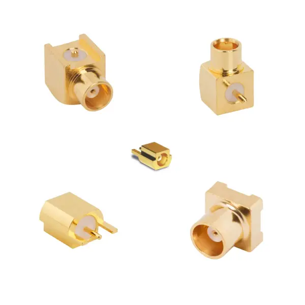

MCX RF connectors: engineering & performance
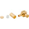
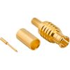
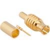
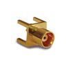
The RF MCX connector series utilizes a push-on coupling mechanism for rapid, threadless mating. Constructed from machined brass or beryllium copper, these connectors provide strong mechanical retention and signal integrity. Their miniature footprint allows engineers to maximize PCB density and streamline complex cabling structures.
The 50 Ω MCX RF connectors deliver stable performance from DC to 12 GHz, while specific 75 Ω variants are optimized for 12G broadcast applications up to 18 GHz. Utilizing PTFE insulators and gold-plated contacts, they maintain a maximum insertion loss of 0.10 dB at 1 GHz. Furthermore, RF leakage is strictly limited to -60 dB. Finally, full compliance with the CECC 22220 specification ensures standard interoperability across diverse RF ecosystems.
MCX coax connector specifications
Review the electrical, mechanical, and material parameters in the three tables below.
RF MCX connector electrical specifications
Parameter | 50 Ω Specification | 75 Ω Specification |
Impedance | 50 Ω Nominal | 75 Ω Nominal |
Frequency Range | DC - 12 GHz | DC - 6 GHz (0-18 GHz on 12G Products) |
Voltage Rating (Max Continuous) | 225 VRMS | 170 VRMS |
Dielectric Withstanding Voltage (Max) | 1000 VRMS | 500 VRMS |
VSWR (Return Loss) | 1.3 (-18 dB) Max (DC-6 GHz) | 1.22 (-20 dB) Max (12G Products: DC-6 GHz) 1.43 (-15 dB) Max (12G Products: 6-12 GHz) |
Insulation Resistance | 10000 MΩ Min | 10000 MΩ Min |
Center Contact Resistance | 5 mΩ Min | 5 mΩ Min |
Outer Contact Resistance | 1 mΩ Min | 2.5 mΩ Min |
RF Leakage | -60 dB Max @ 1 GHz | -60 dB Max @ 1 GHz |
Insertion Loss | 0.10 dB Max @ 1 GHz | 0.10 dB Max @ 1 GHz |
Power Handling | 95 W Max @ 1 GHz @ 25 °C | 95 W Max @ 1 GHz @ 25 °C |
MCX coaxial connector mechanical specifications
Parameter | 50 Ω Specification | 75 Ω Specification |
Mating Cycles | 500 Min | 500 Min |
Coupling Mechanism | Push-On | Push-On |
Interface Specification | CECC 22220 | CECC 22220 |
Engagement Force | 20 N Max | 10 N Max |
Disengagement Force | 10 N Min | 10 N Min |
MCX connector material & environmental specifications
Parameter | Specification |
Body Material | Brass, Beryllium Copper |
Body Plating Options | Gold, Nickel, White Bronze, Bright Tin, Nickel/Matte Tin, Gold/Nickel |
Center Contact | Brass, Beryllium Copper, Phosphor Bronze (Gold Plated) |
Insulator | PTFE, Delrin |
Operating Temperature Range | -65 °C to +165 °C (May vary based on configuration) |
Thermal Shock | MIL-STD-202, Method 107 (Test Condition B) |
Corrosion | MIL-STD-202, Method 101 (Test Condition B) - 5% Salt Solution |
Vibration & Mechanical Shock | MIL-STD-202, Method 204 & 213, Snap-On (Test Condition B) |
PFAS Status | Contains PFAS (variant dependent) |