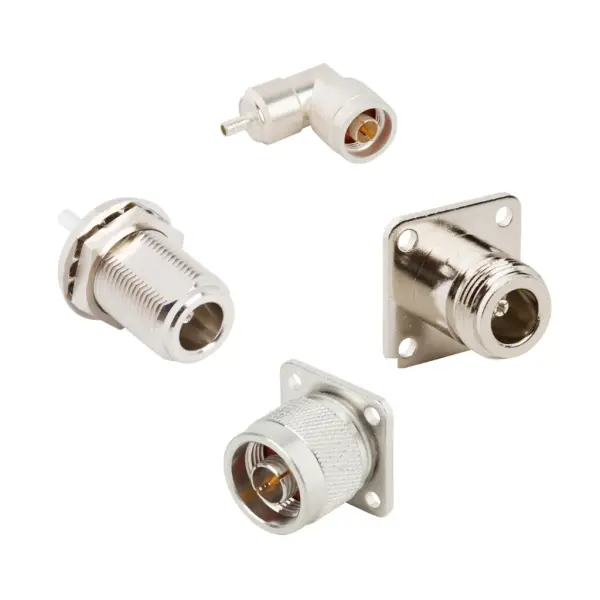

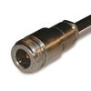

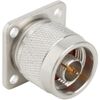
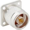
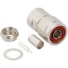
N-Type coax connector: engineering & RF performance
RF N-Type connectors are constructed with brass bodies available in gold or nickel plating. By utilizing PTFE or styrene insulators, this configuration ensures stable electrical performance across various environments.
The 5/8-24 threaded coupling mechanism prevents mechanical disconnects under high vibration, withstanding a minimum retention force of 100 lbs. For reliable and secure installation, the recommended mating torque is 8 to 12 in-lbs.
Coax N connector standard configurations operate from DC to 11 GHz, while extended-range designs maintain signal integrity up to 18 GHz. They support high-power requirements with a 300 W capacity at 10 GHz and a low PIM of -166 dBc. Additionally, these connectors seamlessly accommodate industry-standard coaxial cables including RG-213, LMR-400, RG-55, and RG-174.
RF N-Type connector specifications
Explore the electrical, mechanical, material, and environmental parameters of the N-Type coax connector series.
Type N connector electrical specifications
Parameter | Value |
Impedance | 50 Ω |
Frequency Range (Standard) | DC to 11 GHz |
Frequency Range (Extended) | DC to 18 GHz |
Voltage Rating | 500 VRMS Continuous |
Dielectric Withstanding Voltage | 1500 VRMS Max |
VSWR (Straight) | 1.30 (-18 dB) Max (DC to 11 GHz) |
VSWR (Right Angle) | 1.35 (-16 dB) Max (DC to 9 GHz) |
VSWR (Right Angle) | 1.50 (-14 dB) Max (9 to 11 GHz) |
Insulation Resistance | 5000 MΩ Min |
Center Contact Resistance | 1 mΩ Max |
Outer Contact Resistance | 4 mΩ Max |
RF Leakage | -90 dB Max (DC to 3 GHz) |
Insertion Loss (Straight) | 0.15 dB Max (DC to 9 GHz) |
Insertion Loss (Right Angle) | 0.30 dB Max (DC to 10 GHz) |
Passive Intermodulation (PIM) | -166 dBc (2 x 43 dBm inputs) |
Power Handling | 300 W at 10 GHz at 25 °C |
Coax N connector mechanical specifications
Parameter | Value |
Mating Cycles | 500 Min |
Coupling Mechanism | Threaded |
Interface Specification | MIL-STD-348 |
Coupling Retention Force | 100 lbs Min |
Mating Torque (Min Working) | 8 to 12 in-lbs |
N-Type coaxial connector material specifications
Parameter | Value |
Body Material | Brass |
Body Plating | Gold or Nickel |
Insulator Material | PTFE or Styrene |
Contact Material | Phosphor Bronze |
RF N connector environmental specs & compliance
Parameter | Value |
Temperature Range (Typical) | -65 °C to +165 °C |
Temperature Range (Styrene) | -40 °C to +85 °C |
Thermal Shock | MIL-STD-202, Method 107 (Test Condition B) |
Corrosion | MIL-STD-202, Method 101 (Test Condition B) |
Vibration | MIL-STD-202, Method 204 (Test Condition B) |
Mechanical Shock | MIL-STD-202, Method 213 (Test Condition I) |
Moisture Resistance | MIL-STD-202, Method 106 |
Altitude | MIL-STD-202, Method 105 (Test Condition C) |