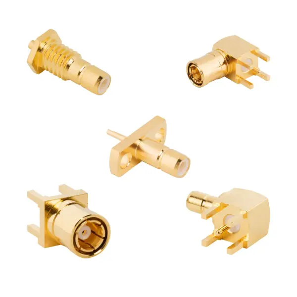

SMB coax connectors: high-density architecture
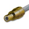
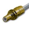
The RF SMB connector series integrates a subminiature form factor with a snap-on coupling mechanism. This design enables rapid mating in space-constrained architectures where standard threaded interfaces become impractical.
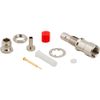
The housings of these SMB coax connectors are manufactured from Brass, Zinc Diecast, Zamac, or Beryllium Copper. This ensures mechanical stability and reliable RF shielding. For the center contacts, Beryllium Copper or Brass is utilized with Gold plating to actively combat corrosion.
Engineers can specify Gold, Nickel, Bright Tin, or White Bronze body plating to match specific environmental requirements. Internally, PTFE dielectric insulators consistently maintain a stable 50 Ω impedance.
SMB RF connector specifications
Review the exact electrical parameters, material compositions, and environmental ratings for SMB series interconnects.
SMB coaxial connector electrical specifications
Parameter | Specification |
Impedance | 50 Ω |
Frequency Range | DC to 4 GHz (DC to 10 GHz on Extended Range) |
Voltage Rating | 335 VRMS Continuous |
Dielectric Withstanding Voltage | 1000 VRMS Max |
VSWR (Straight, RG178/196) | 1.30 + 0.04 f (GHz) |
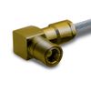
VSWR (Right Angle, RG178/196) | 1.45 + 0.06 f (GHz) |
VSWR (Straight, RG174/316/188) | 1.25 + 0.04 f (GHz) |
VSWR (Right Angle, RG174/316/188) | 1.35 + 0.04 f (GHz) |
Insulation Resistance | 1000 MΩ Min |
Center Contact Resistance | 6 mΩ Max |
Outer Contact Resistance | 1 mΩ Max |
RF Leakage | -120 dB Max (DC to 3 GHz) |
Insertion Loss (Straight) | 0.30 dB @ 1.5 GHz Max |
Insertion Loss (Right Angle) | 0.60 dB @ 1.5 GHz Max |
Power Handling | 95 W @ 1 GHz @ 25 °C |
RF SMB connector mechanical specifications
Parameter | Specification |
Mating Cycles | 500 Min |
Coupling Mechanism | Snap-On |
Interface Specification | MIL-STD-348 |
Engagement Force | 14 lbs (62 N) Max |
Disengagement Force | 2 lbs (8.9 N) Max |
Coupling Torque | Not Applicable (Snap-On) |
SMB series material specifications
Parameter | Specification |
Body Material | Brass, Zinc Diecast, Zamac, Beryllium Copper |
Body Plating | Gold, Nickel, Bright Tin, White Bronze, Tin |
Center Contact Material | Brass, Beryllium Copper |
Center Contact Plating | Gold |
Insulator | PTFE |
SMB RF connector environmental specs & compliance
Parameter | Specification |
Temperature Range | -65 °C to +165 °C |
Thermal Shock | MIL-STD-202 Method 107 (Condition B), except high temp @ +200 °C |
Corrosion (Salt Spray) | MIL-STD-202 Method 101 (Condition B) 5% Salt Solution |
Vibration | MIL-STD-202 Method 204, snap-on (Condition B) 15 G |
Mechanical Shock | MIL-STD-202 Method 213, snap-on (Condition B) 75 G @ 6 ms 1/2 sine |
Moisture Resistance | MIL-STD-202 Method 106 |
Altitude | MIL-STD-202 Method 105 (Condition C) |
IP Rating | IP68 (variant dependent) |