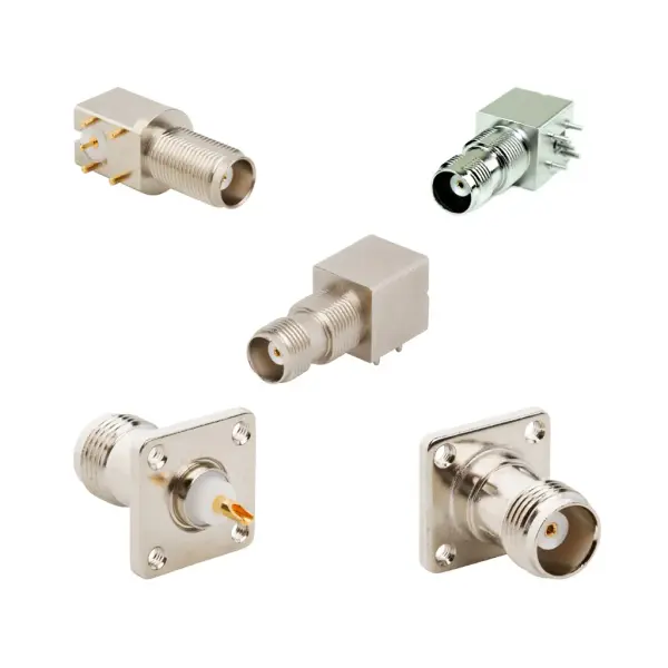
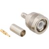

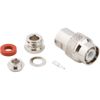
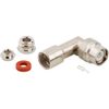
TNC coax connectors technical overview
RF TNC connectors utilize a 7/16"-28 threaded coupling mechanism to prevent physical disconnects under high vibration and mechanical stress. Securing this interface requires a mating torque of 4 to 6 in-lbs (0.51 - 0.67 N-m). This stable connection satisfies MIL-STD-202 (Method 213, Condition G), ensuring zero electrical discontinuity during mechanical shock. Additionally, the interface dimensions strictly comply with the MIL-STD-348 specification.
To optimize conductivity, TNC RF connectors feature gold or silver-plated contacts. This maintains a maximum center contact resistance of 1.5 mΩ and an outer resistance of 0.2 mΩ. The robust assembly supports power handling up to 316 W at 1 GHz (25 °C). Furthermore, standard straight designs exhibit a maximum insertion loss of just 0.18 dB at 9 GHz.
RF TNC connector specifications
Access the complete technical parameters of the TNC connector series across the four tables below.
TNC coax connector electrical specifications
Parameter | Specification |
Impedance | 50 Ohm / 75 Ohm |
Frequency Range | DC - 11 GHz (Standard) / DC - 18 GHz (Extended) |
Voltage Rating | 500 Volts Peak |
Dielectric Withstanding Voltage | 1500 VRMS Max |
VSWR (Return Loss) | 1.3 (-18 dB) Max (DC - 11 GHz) |
Insulation Resistance | 5000 MΩ Min |
Center Contact Resistance | 1.5 mΩ Max |
Outer Contact Resistance | 0.2 mΩ Max |
RF Leakage | -60 dB Max @ 3 GHz |
Insertion Loss (Straight) | 0.18 dB Max @ 9 GHz |
Insertion Loss (Right Angle) | 0.21 dB Max @ 9 GHz |
Power Handling | 316 W @ 1 GHz @ 25 °C |
TNC RF connector mechanical specifications
Parameter | Specification |
Coupling Mechanism | 7/16"-28 Threaded |
Mating Cycles | 500 Min |
Interface Specification | MIL-STD-348 |
Mating Torque | 4 - 6 inch-pounds (0.51 - 0.67 N-m) |
Polarity Formats | Standard / Reverse Polarity |
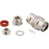
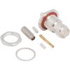
Mounting Styles | Bulkhead / Panel Mount |
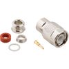
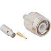
Cable Terminations | Crimp / Clamp |
Supported Coaxial Cables | RG-58, RG-142, RG-316 |
TNC coaxial connector material specifications
Parameter | Specification |
Contact Plating | Gold / Silver |
Body Material | Brass / Zinc Diecast |
Body Plating | Nickel / Silver / Tin / Gold / White Bronze |
Insulator Material | PTFE / Delrin / Nylon / Polypropylene |
Coax TNC connector environmental specs & compliance
Parameter | Specification |
Temperature Range | -65 °C to +165 °C |
Thermal Shock | MIL-STD-202, Method 107 (Condition B) |
Corrosion | MIL-STD-202, Method 101 (Condition B) - 5% Salt |
Vibration | MIL-STD-202, Method 204 (Condition B) |
Mechanical Shock | MIL-STD-202, Method 213 (Condition G) |
Moisture Resistance | MIL-STD-202, Method 106 |
Altitude | MIL-STD-202, Method 105 (Condition C) |
Environmental Sealing | IP67 sealed versions available |