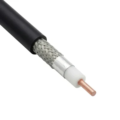
LMR 400 Flexible Coaxial Cable
P/N: 10077860
LMR-400 cable is a 50 Ω flexible low-loss coaxial cable for outdoor RF systems, antenna feeder runs, and wireless communication equipment. It supports frequencies up to 8 GHz, provides typical attenuation of 12.8 dB/100 m at 900 MHz, and offers more than 90 dB shielding effectiveness. The cable has a 10.29 mm outer diameter, a 101.6 mm repeated minimum bend radius, 16 kW peak power handling, and an operating temperature range of −40°C to +85°C.
Key Engineering Specs
Comprehensive Specifications
| Impedance | 50 Ω |
|---|---|
| Voltage Withstand | 2500 VDC |
| Peak Power | 16 kW |
| Shielding Effectiveness | > 90 dB |
| Dielectric Constant | 1.38 |
| Velocity Of Propagation | 84 % |
| Time Delay | 3.92 ns/m |
| Capacitance | 78.4 pF/m |
| Inductance Uh M | 0.2 µH/m |
| Inner Conductor Dc Resistance | 4.6 Ω/km |
| Outer Conductor Dc Resistance | 5.4 Ω/km |
| Maximum Operating Frequency | 8 GHz |
| Frequency Range | 8 GHz |
| Frequency | Attenuation |
|---|---|
| 30 MHz | 2.3 dB/100m |
| 50 MHz | 2.95 dB/100m |
| 150 MHz | 4.92 dB/100m |
| 220 MHz | 5.91 dB/100m |
| 450 MHz | 8.86 dB/100m |
| 900 MHz | 12.80 dB/100m |
| 1.5 GHz | 16.73 dB/100m |
| 2 GHz | 19.69 dB/100m |
| 2.5 GHz | 22.31 dB/100m |
| 5.8 GHz | 35.43 dB/100m |
| 8 GHz | 42.65 dB/100m |
| K1 | 0.40524 dB/100m |
| K2 | 0.00086 dB/100m |
| Weight | 100 g/m |
|---|---|
| Center Conductor Diameter | 2.74 mm (0.1079 in) |
| Dielectric Diameter | 7.24 mm (0.285 in) |
| Inner Shield Diameter | 7.39 mm (0.2909 in) |
| Outer Braid Diameter | 8.13 mm (0.3201 in) |
| Jacket diameter | 10.29 mm (0.4051 in) |
| Tensile Strength | 72.6 Kg |
| Center Conductor Type | Solid |
|---|---|
| Center Conductor Material | Bare Copper-Clad Aluminum (BCCAI) |
| Inner Shield Material | Aluminum Tape |
| Outer Braid Material | Tinned Copper Braid |
| Dielectric Material | Foam PE |
| Jacket Material | PE |
| Min Bend Radius (Repeated) | 101.6 mm (4 in) |
|---|---|
| Min Bend Radius Installation | 25.4 mm (1 in) |
| Temperature Operating Range | -40 °C / 85 °C |
|---|
| Bending Moment | 0.68 (N.m) |
|---|---|
| Flat Plate Crush | 0.71 (kg/mm) |
| Jacket Spark Voltage | 8000 VRMS |
| Installation Temperature Range | -40 °C / 85 °C |
| Storage Temperature Range | -70 °C / 85 °C |
Description
LMR 400 Cable
LMR 400 cable is a 50 Ω flexible, low-loss coaxial cable designed for outdoor RF transmission systems, wireless communication equipment, antenna feeder runs, and jumper assemblies. Its construction combines a solid copper-clad aluminum center conductor, foam polyethylene dielectric, aluminum tape shielding, tinned copper braid, and a black polyethylene jacket.
This page covers the PE-jacketed LMR-400 configuration. LMR-400-DB, LMR-400-FR, PVC, UltraFlex, and 75 Ω versions are separate cable configurations with different electrical, mechanical, or environmental characteristics.
LMR 400 Cable Loss and Attenuation Model
The attenuation values listed in the Comprehensive Specifications section are the primary reference for LMR-400 cable loss calculations. At 900 MHz, the typical attenuation is 12.8 dB/100 m, which is approximately 0.128 dB per meter or 0.039 dB per foot.
For an estimate at another frequency within the published operating range, the nominal attenuation can be calculated using the following product-specific model:
In this model, f is the frequency in MHz and A100m(f) is the estimated attenuation in dB/100 m. The metric coefficients are K1 = 0.401213911 and K2 = 0.000853018. This model should be used only within the published attenuation reference range up to 8 GHz.
For a complete link-loss estimate, include connector, termination, assembly, and cable-length losses separately. Use measured cable assembly data for the final link budget whenever available.
LMR 400 Cable Specifications
LMR-400 has a 50 Ω impedance, an 84% velocity factor, a 10.29 mm outer diameter, and a maximum operating frequency of 8 GHz. Its minimum installation bend radius is 25.4 mm, while its minimum repeated bend radius is 101.6 mm. These characteristics make it suitable for antenna cables, wireless infrastructure, equipment interconnects, and outdoor RF feeder applications.
LMR 400 Average Power Handling
Peak power and average power are different specifications. The 16 kW peak power value listed in the Comprehensive Specifications section is separate from the following frequency-dependent average-power references.
These values apply at VSWR 1.0, an ambient temperature of +40°C, an inner-conductor temperature of 100°C, sea level, dry air, atmospheric pressure, and no solar loading.
Frequency | Average Power |
|---|---|
30 MHz | 3.33 kW |
50 MHz | 2.57 kW |
150 MHz | 1.47 kW |
220 MHz | 1.20 kW |
450 MHz | 0.83 kW |
900 MHz | 0.58 kW |
1500 MHz | 0.44 kW |
1800 MHz | 0.40 kW |
2000 MHz | 0.37 kW |
2500 MHz | 0.33 kW |
5800 MHz | 0.21 kW |
8000 MHz | 0.1726 kW |
These are frequency-specific manufacturer reference values and should not be treated as a universal continuous operating-power rating. Final power capability depends on duty cycle, ambient temperature, cooling, VSWR, installation conditions, and connector selection.
LMR 400 Cable Connectors
LMR-400 cable assemblies can be terminated with N-type, SMA, BNC, TNC, 7/16 DIN, HN, UHF, Mini-UHF, QN, and 4.1/9.5 mini-DIN connectors.
For an LMR 400 cable with an N-type male connector, the manufacturer lists straight, right-angle, and reverse-polarity configurations. SMA male and SMA female straight connector options are also documented for LMR-400 cable assemblies. The final connector should be selected according to interface gender, operating frequency, VSWR, power level, and mechanical requirements.
LMR 400 Cable Prep Tools and Crimp Tools
LMR-400 cable preparation and connector installation may require tools matched to the selected connector design. Documented options include the CST-400 and ST-400C-2 prep tools, CT-400/300 and CT-U crimp tools, Y1719 crimp dies, CCT-02 cutting tools, DBT-U deburring tools, GST-400 grounding-strap preparation tools, and the TK-400EZ tool kit.
LMR 400 Cable, UltraFlex, and 75 Ω Versions
The LMR-400 cable described on this page is a 50 Ω cable. LMR-400-75 is a separate 75 Ω product and should not be treated as electrically interchangeable with the 50 Ω version.
LMR-400-UF, or UltraFlex, is a separate construction with a stranded center conductor for applications requiring increased flexibility or repeated bending. Its attenuation and mechanical characteristics differ from those of LMR-400 and should be evaluated separately.
LMR 400 Cable Price
LMR 400 cable price per meter depends on cable quantity, jacket configuration, cable length, connector type, and whether the cable is supplied in bulk or as a terminated assembly. Contact iPrece for current pricing, availability, connector options, and custom cable lengths.
LMR 400 Cable Applications
Typical applications include wireless communication systems, GPS, WLAN, WISP, WiMAX, SCADA, mobile antennas, outdoor RF equipment, short antenna feeder runs, and other systems requiring a flexible, low-loss 50 Ω coaxial cable.
For a defined cable length, N-type male or SMA connector configuration, or pre-terminated RF cable assembly, request an application-specific quotation from iPrece.
Engineering Downloads
Related Products
Show more
Need Design Assistance?
Our RF engineers can verify your PCB footprint, stackup, or interface compatibility. Get direct support to ensure optimal signal integrity.