Coaxial Cable Alternatives for Your Application


The most commonly discussed coaxial cable alternatives are:
Fiber optic cable: For long-distance, high-capacity data transmission and electrical isolation.
Twisted pair cable: For balanced signaling in networking, telecommunications, and industrial communication.
Ethernet cable: For connecting devices to wired local area networks, typically using twisted-pair copper cabling.
HDMI cable: For transmitting digital video, multichannel audio, and control information between compatible devices.
RCA cable: For connecting analog audio, composite video, and certain digital audio interfaces.
Cable or Interface | Main Advantage | Primary Applications | Main Limitation |
Coaxial Cable | Controlled-impedance, shielded RF transmission | RF equipment, antennas, CATV, SDI video | Frequency-dependent attenuation |
Fiber Optic | Long reach, high capacity, electrical isolation | Telecom, network backbones, data centers | Requires optical transceivers |
Twisted Pair | Balanced transmission and noise rejection | Data networks, RS-485, telephony | Distance and crosstalk constraints |
Ethernet Cable | Standardized network connectivity | LANs, computers, switches, IP cameras | Copper link length limits |
HDMI Cable | Integrated digital video and audio | TVs, monitors, AV equipment | High-rate links can be length-sensitive |
RCA Cable | Simple connector-based audio/video connections | Analog audio, composite video, S/PDIF | Performance depends on cable and interface |
Technical note: Ethernet and HDMI are interface families rather than single cable constructions. RCA specifies a connector, and a cable with RCA connectors may itself be coaxial.
The best coaxial cable alternative depends on the application. Fiber optic is generally preferred for long-distance network backbones because it combines high data capacity with low attenuation. Twisted pair is widely used for differential communication because it provides effective noise rejection without requiring a coaxial shield. Ethernet cabling supports standardized computer networking, while HDMI is designed for digital audio/video connections. RCA, meanwhile, describes a connector rather than a distinct cable transmission technology.
Coaxial cable remains important in RF and microwave systems, cable television, broadband distribution, and professional video because its controlled impedance and shielded structure support predictable high-frequency signal transmission.
Coaxial Cable vs Fiber Optic
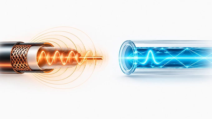
The most important difference between coaxial cable and fiber optic cable is the physical mechanism used to transmit information; A coaxial cable carries electrical signals through a metallic transmission-line structure. Fiber optic cable carries information through modulated light guided inside a transparent core.
This difference affects bandwidth, transmission distance, electromagnetic interference, electrical isolation, and the equipment required at each end.
Transmission Technology: Electrical vs. Light
A coaxial cable consists of a center conductor, dielectric insulation, an outer conductor or shield, and a protective jacket. The electromagnetic signal propagates through the transmission-line structure, with its fields primarily distributed in the dielectric region between the center and outer conductors.
For an ideal coaxial line, the characteristic impedance is approximately:
Where:
is the characteristic impedance.
is the relative permittivity of the dielectric.
is the radius of the inner conductor.
is the inner radius of the outer conductor.
Typical coaxial systems use 50 Ω or 75 Ω cables, although other impedances exist.
Fiber optic cable uses a different structure. Its core and cladding have different refractive indices, allowing light to propagate through guided optical modes. Optical transceivers convert electrical data into modulated light at the transmitting end and recover electrical information at the receiver. Because the optical transmission medium is dielectric, a suitable nonconductive fiber link does not provide an electrical conduction path between connected equipment. This is particularly valuable when connecting equipment across different grounding environments.
Practical distinction: Coaxial cable is usually the more direct solution for carrying an analog RF signal between a transmitter, receiver, instrument, and antenna. Fiber is better suited to transporting information over long distances, but an RF-over-fiber link requires appropriate electro-optical and optoelectronic conversion hardware.
Coaxial Cable vs Fiber Optic Speed
When comparing coaxial cable and fiber optic speed, fiber optic is significantly faster in terms of data transmission capacity, supporting much higher bandwidth and data rates over longer distances with lower attenuation.
However, signal propagation speed tells a different story. Light travels through standard silica fiber at approximately 67% of the speed of light in vacuum, while electromagnetic signals in coaxial cables typically propagate at 66–90%, depending on the dielectric material. Therefore, fiber optic offers superior data throughput, but its signals do not necessarily travel faster than those in coaxial cables.
When evaluating fiber optic as a coaxial cable alternative, it generally offers greater practical data capacity over long distances, but it is incorrect to assign a fixed maximum speed to either cable medium.
A cable's achievable data rate depends on the signaling standard, available bandwidth, modulation method, attenuation, receiver sensitivity, and signal-processing capabilities.
For example:
Transmission System | Representative Rate | Specified or Example Distance |
MoCA 2.5 over coax | Up to 2.5 Gbps MAC throughput | Depends on coax network |
12G-SDI over 75 Ω coax | 11.88 Gb/s serial rate | About 70 m with a specified cable and receiver |
10GBASE-LR over single-mode fiber | 10 Gb/s Ethernet | Up to 10 km |
10GBASE-SR over OM4 fiber | 10 Gb/s Ethernet | Up to 400 m |
These values describe particular systems, not universal limits of coaxial cable or optical fiber. MoCA 2.5's throughput is also a shared-network capability and should not be interpreted as a guaranteed 2.5 Gb/s application data rate for every connected device.
The transmission rate of 12G-SDI demonstrates that coaxial cable can carry multi-gigabit serial signals. Meanwhile, optical systems can support substantially greater aggregate capacities through advanced transceivers and wavelength-division multiplexing.
Why does fiber support longer distances?
Coaxial cable experiences conductor and dielectric losses that generally increase with operating frequency. At high frequencies, skin effect increases the effective resistance of the metallic conductors. Dielectric loss also contributes to signal attenuation.
Fiber optic transmission avoids metallic conductor loss along the optical path. Its attenuation is instead determined by mechanisms such as material absorption, scattering, bending, and optical connector losses.
For a fiber link, attenuation is commonly specified in dB/km at a particular optical wavelength. For coaxial cable, attenuation is commonly specified in dB per unit length at particular electrical frequencies. In either case, the usable distance depends on the complete link budget.
Which should you choose?
Consider fiber optic as a coaxial cable alternative when connecting buildings, extending network backbones, or transmitting large amounts of data over long distances.
Use coaxial cable when the equipment has native coaxial RF ports, when the transmitted quantity is an analog RF waveform, or when an existing coaxial distribution network already supports the required service.
Digital Audio: Coaxial vs Optical Cable
In consumer audio, the phrase coaxial vs optical cable usually refers to two physical implementations of S/PDIF digital audio.
These are:
Coaxial S/PDIF: Electrical digital audio, typically carried through a nominal 75 Ω coaxial connection with RCA connectors.
Optical S/PDIF: Digital audio transmitted through a TOSLINK optical connection, commonly using plastic optical fiber.
Both can transport the same S/PDIF audio data formats when supported by the connected devices.
They commonly support two-channel uncompressed PCM audio and compatible compressed multichannel bitstreams. Support for sampling rates and specific encoded formats depends on the equipment.
Neither conventional S/PDIF connection should be assumed to support the same high-bandwidth multichannel audio capabilities as HDMI.
Does optical audio sound better than coaxial audio?
Not inherently. If both interfaces deliver the same digital audio samples without errors, the transmitted audio information is identical.
Optical transmission provides electrical isolation, which can help prevent unwanted ground-current paths between audio devices. Coaxial S/PDIF uses an electrical connection and may be more convenient where compatible ports and cables are already available.
Receiver clock recovery, jitter rejection, and interface implementation can affect system behavior, but the cable medium alone does not establish superior audible quality.
An additional distinction matters: TOSLINK optical audio is not equivalent to a high-capacity single-mode telecom fiber connection. Both use light, but their transceivers, optical media, and supported interfaces differ substantially.
Coaxial Cable vs Twisted Pair
Coaxial and twisted pairs are both copper-based electrical transmission media, but their conductor arrangements and signaling methods differ.
Coaxial cable is commonly used for single-ended, controlled-impedance RF transmission. A twisted pair is commonly used for balanced and differential communication. This difference is especially important in networking, industrial communication, instrumentation, and electrically noisy environments.
Balanced vs. Unbalanced Lines
A coaxial transmission line contains a center conductor surrounded by an outer conductor.
In a conventional single-ended coaxial system, the signal voltage is measured between the center conductor and the outer conductor. The outer conductor forms part of the signal-return path and provides electromagnetic shielding.
A twisted pair contains two insulated conductors twisted around one another. In a balanced communication system, the receiver primarily responds to the voltage difference between the two conductors.
For a differential receiver:
An interfering voltage that couples similarly into both conductors appears largely as common-mode voltage. A well-balanced receiver can reject much of that common-mode interference. The effectiveness of this rejection depends on line balance, termination symmetry, receiver common-mode rejection, and cable installation. Twisting helps maintain similar electromagnetic exposure for both conductors, improving the line's balance over distance.
Engineering implication: Balanced twisted-pair systems are well suited to communication standards such as Ethernet and RS-485. Coaxial cable is more directly suited to single-ended RF interfaces with defined characteristic impedances.
The two cable types should not be interchanged without considering the signaling interface. A balun or other interface conversion may be required when transitioning between balanced and unbalanced systems.
Shielding and EMI/RFI Immunity
Coaxial cable provides an outer conductive shield around the signal conductor. When properly designed and terminated, this shield reduces electromagnetic coupling between the internal signal path and the external environment. However, shielding effectiveness depends on several factors:
Outer-conductor construction and coverage
Transfer impedance and shield continuity
Connector and termination quality
Operating frequency
Cable routing and grounding arrangement
A damaged shield or poorly terminated connector can compromise interference rejection.
Twisted pair cabling uses a different approach. Unshielded twisted pair (UTP) relies primarily on line balance, conductor twisting, and differential reception to reject interference. A shielded twisted pair (STP) adds a conductive shield to provide another level of protection, although its effectiveness still depends on appropriate installation and grounding. Neither medium is universally immune to interference.
A well-designed differential twisted-pair system can reject noise effectively even without a shield, while a properly constructed coaxial line can offer excellent shielding for high-frequency RF signals.
Which Is Better for High-Frequency Signals?
For conventional RF equipment operating through 50 Ω or 75 Ω ports, coaxial cable is generally the more suitable direct connection. Its geometry supports a controlled characteristic impedance and predictable transmission-line performance over the intended frequency range.
Twisted pairs can also support high-frequency electrical signaling, as demonstrated by multi-gigabit Ethernet technologies. However, those systems rely on differential transceivers and signal-processing techniques designed specifically for the cable and channel characteristics.
Choose coaxial cable for RF measurement equipment, antenna feeds, microwave signal paths, and other compatible single-ended RF connections. Choose twisted pairs as a practical coaxial cable alternative for differential digital communication, industrial fieldbus connections, and networking applications where balanced transmission is part of the interface specification.
Coaxial Cable vs Ethernet Cable
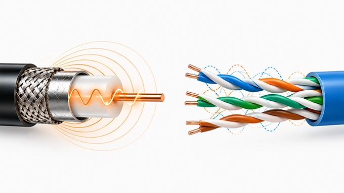
The comparison between coaxial cable and Ethernet cable requires an important clarification: Ethernet is a family of networking technologies, not a single type of cable.
In everyday use, an Ethernet cable usually means Category-rated twisted-pair cabling terminated with modular eight-position connectors, commonly called RJ45 connectors. However, Ethernet can also operate over fiber optic links, twinaxial connections, and historically, coaxial cable.
The meaningful comparison is therefore between coaxial cabling and modern twisted-pair Ethernet cabling for a particular networking application.
A Brief History: Thinnet and Thicknet Coaxial Cables
Early Ethernet systems used coaxial cable as a shared communication medium. Two historically important versions were:
10BASE5 (Thicknet)
10BASE5 used relatively thick 50 Ω coaxial cable and supported 10 Mb/s Ethernet communication over a bus segment up to 500 meters long.
Devices connected to a shared cable through appropriate transceiver arrangements.
10BASE2 (Thinnet)
10BASE2 used a thinner 50 Ω coaxial cable, commonly associated with RG-58, and supported 10 Mb/s operation over a maximum segment length of 185 meters.
BNC T-connectors were commonly used to connect network stations. Both systems required appropriate termination at the ends of the shared coaxial segment. A fault or discontinuity in the common bus could disrupt communication for multiple connected devices.
Modern Ethernet installations largely moved away from these shared coaxial topologies toward point-to-point links connected through network switches.
Modern LANs: Coaxial vs Ethernet Cable Speed
Modern twisted-pair Ethernet supports substantially higher rates than historical coaxial Ethernet.
For example:
Ethernet Technology | Common Cable Requirement | Nominal Link Rate | Standard Channel Length |
100BASE-TX | Cat5 or better | 100 Mb/s | 100 m |
1000BASE-T | Cat5e or better | 1 Gb/s | 100 m |
10GBASE-T | Cat6A | 10 Gb/s | 100 m |
These figures describe compliant channels with suitable network equipment and installation quality.
Cat6 can also support 10GBASE-T over shorter distances under appropriate conditions, but Cat6A is the usual choice for a new full-length 100-meter 10GBASE-T channel.
Can coaxial cable still carry Ethernet traffic?
Yes. Technologies such as MoCA allow networking data to travel through existing coaxial cabling.
For example, a MoCA 2.5 network supports up to 2.5 Gb/s aggregate MAC throughput under suitable operating conditions. MoCA adapters can bridge between Ethernet ports and a compatible coaxial network.
This can be useful in buildings where coaxial cables already connect several rooms and installing new network cabling would be difficult. However, a MoCA link is not the same as simply connecting a standard Ethernet port to a coaxial cable through a passive connector adapter.
The signal must be converted and transmitted using the appropriate physical-layer technology. Similarly, cable broadband services use dedicated modem technologies to transmit networking data over coaxial distribution infrastructure.
When Should You Choose Coax or Ethernet Cabling?
For a new wired office or home LAN, twisted-pair Ethernet cabling is usually the straightforward choice. It provides direct compatibility with standard network interfaces and can support Power over Ethernet (PoE) where suitable equipment is used.
Coaxial cabling becomes attractive when existing infrastructure can be reused through compatible networking equipment. It also remains appropriate for RF distribution systems where the signal itself must be transmitted through a controlled-impedance coaxial connection.
Coaxial Cable vs HDMI
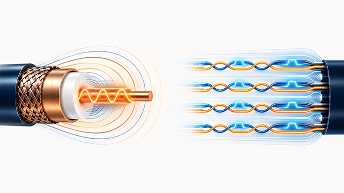
Coaxial cable and HDMI are often compared in audio/video applications, but they describe different technical concepts.
Coaxial cable is a physical transmission medium. HDMI is a digital interface specification that defines audio/video data transmission, control functions, signaling behavior, and connector requirements.
For professional video, the more useful comparison is often between coaxial SDI and HDMI, since both can carry digital video between compatible devices.
Signal Architecture: Serial vs. Parallel
A conventional coaxial SDI connection carries digital video using a high-speed serial signal over one coaxial transmission line.
HDMI uses multiple high-speed differential signal pairs within a single cable assembly. Earlier HDMI signaling uses Transition-Minimized Differential Signaling (TMDS), typically with three high-speed data pairs and a separate clock pair.
Modern HDMI implementations also support Fixed Rate Link (FRL) signaling, which can distribute data across three or four high-speed lanes. Therefore, describing HDMI simply as a parallel interface and coaxial SDI as a serial interface is technically misleading.
Both employ high-speed serial signaling at the lane level. The difference is that coaxial SDI uses a single serial transmission path, while HDMI uses multiple coordinated serial data lanes and additional control connections.
HDMI also provides features associated with consumer and professional displays, such as device identification, content protection, and equipment control. A coaxial cable cannot provide these HDMI functions merely because it has sufficient electrical bandwidth. The endpoints must support the relevant communication protocol.
Distance Limitations and Bandwidth
The usable distance of both coaxial SDI and HDMI depends on cable construction, signal rate, transmitter output, receiver equalization, and acceptable signal integrity.
For coaxial SDI, the interface's serial data rate and cable attenuation provide important design constraints.
Representative SDI rates include:
SDI Interface | Nominal Serial Rate |
HD-SDI | 1.485 Gb/s class |
3G-SDI | 2.97 Gb/s class |
6G-SDI | 5.94 Gb/s class |
12G-SDI | 11.88 Gb/s class |
A 12G-SDI receiver with suitable equalization may support a run of approximately 70 meters using a specified professional 75 Ω coaxial cable. This is an example of an equipment-and-cable combination, not a universal maximum distance for every 12G-SDI link.
HDMI uses different cable categories and transmission capabilities. For example:
Premium High Speed HDMI Cable: Supports link bandwidth up to 18 Gb/s (suitable for 4K/60Hz).
Ultra High Speed HDMI Cable: Supports link bandwidth up to 48 Gb/s (under the HDMI 2.1 specification), capable of supporting uncompressed 8K/60Hz.
These are nominal interface signaling capabilities, not direct measures of uncompressed video payload throughput. Effective throughput can be significantly higher when utilizing Display Stream Compression (DSC). A higher HDMI data rate also does not establish a fixed supported cable length. As signaling rates increase, passive copper cable length becomes more constrained by attenuation, reflections, inter-pair skew, and crosstalk.
Active HDMI cables and optical HDMI cable assemblies can extend the available distance, provided they are compatible with the intended devices and video modes.
Consumer vs. Professional Use Cases
HDMI is generally the more direct option for consumer video equipment.
Typical applications include:
Televisions and monitors
Gaming consoles
Media players
Computers and projectors
AV receivers
HDMI can carry high-resolution digital video and supported multichannel audio over a single connection.
Coaxial SDI is widely used in professional broadcast and production environments.
Typical applications include:
Broadcast cameras
Video routers
Production switchers
Studio monitoring systems
Professional video infrastructure
Professional SDI connections commonly use 75 Ω coaxial cable with locking BNC connectors. This provides a mechanically secure connection and predictable electrical interface for equipment designed around SDI.
Can You Connect Coaxial Video Directly to HDMI?
Not with a simple passive cable.
SDI and HDMI use different signaling formats and interface requirements. A connection between an SDI output and an HDMI input requires an appropriate active converter. The converter must support the specific video format, frame rate, color representation, and other relevant interface requirements. The same principle applies when converting HDMI to SDI.
Coaxial Cable vs RCA
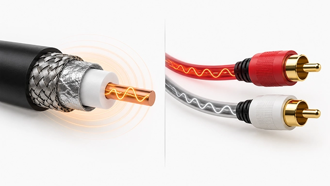
The comparison between coaxial cable and RCA is different from the previous comparisons. Coaxial describes the cable's internal conductor geometry, while RCA describes a connector type. A cable fitted with RCA connectors may itself contain coaxial cable. Therefore, coaxial and RCA are not necessarily competing cable technologies.
Connector vs. Cable Type
An RCA connector is a single-contact, unbalanced connector interface consisting of a center contact and an outer conductive connection. It is commonly used in analog audio, composite video, and coaxial digital audio equipment.
Coaxial cable refers to the internal cable structure, which includes a center conductor, dielectric, and surrounding outer conductor. The two terms describe different characteristics.
For example, a 75 Ω coaxial cable may be terminated with RCA connectors for S/PDIF digital audio.
A different coaxial cable may use BNC connectors for professional video or SMA connectors for RF measurement equipment. Likewise, a cable assembly sold as an RCA audio cable may contain a shielded conductor arrangement, but its actual impedance and high-frequency performance depend on its construction.
The connector alone does not guarantee that the assembly is suitable for a particular RF or digital transmission standard.
Digital Audio (S/PDIF) vs. Analog Stereo
RCA connectors are used for two fundamentally different audio signal types.
1- Analog stereo audio
A conventional analog stereo connection commonly uses two RCA cable assemblies:
Left-channel audio
Right-channel audio
Each connection carries an analog voltage waveform representing the corresponding audio channel. These are generally unbalanced, line-level connections and are not normally specified as 75 Ω transmission systems at audio frequencies.
2- Coaxial S/PDIF audio
Coaxial S/PDIF carries digitally encoded audio over a nominal 75 Ω electrical interface. It commonly uses a single RCA cable assembly.
The signal is not conventional analog audio, even though the connector may look identical to an analog RCA audio connector.
A 75 Ω coaxial cable and suitable 75 Ω connectors help maintain the intended transmission-line characteristics.
Can You Use an RCA Cable Instead of a Coaxial Cable?
The answer depends on the interface.
For a short analog line-level audio connection, a suitable RCA audio cable is normally appropriate.
For coaxial S/PDIF, a 75 Ω coaxial cable assembly is the preferred engineering choice. For RF or microwave transmission, the cable must meet the required characteristic impedance, frequency range, shielding, attenuation, and connector specifications.
An RCA connector's physical compatibility with a device does not establish electrical compatibility with the signal. The same caution applies when connecting 50 Ω RF equipment to 75 Ω systems.
Even if a mechanical adapter allows two connectors to mate, an impedance discontinuity may introduce reflections that affect RF performance.
Which Coaxial Cable Alternative Should You Choose?
The correct cable depends first on the signal or interface being transmitted. Bandwidth and maximum distance become meaningful only after the system's electrical or optical requirements are defined.
Selection Guide by Application
Application | Recommended Medium or Interface | Main Reason |
Antenna to RF receiver | 50 Ω coaxial cable, where specified | Compatible RF impedance |
Long-distance network backbone | Fiber optic | Long reach and high capacity |
Office computer networking | Cat6A twisted-pair Ethernet | Standardized 10GBASE-T connectivity |
Networking through existing coax | MoCA with compatible coax | Reuses installed infrastructure |
Industrial RS-485 communication | Suitable twisted pair | Differential signal transmission |
Television or gaming display | HDMI | Integrated digital video and audio |
Professional broadcast video | 75 Ω coaxial SDI | Standardized video interface |
Short analog stereo connection | RCA-terminated audio cables | Compatible line-level connection |
Digital audio with ground-isolation needs | Optical TOSLINK S/PDIF | No electrical signal connection |
Microwave test equipment | Specified RF coaxial assembly | Controlled impedance and RF performance |
These recommendations assume the connected equipment supports the indicated interface.
1. Start With Signal Type and Interface Compatibility
Before selecting any coaxial cable alternative, identify what the system must actually transmit. Is it an analog RF signal, a differential digital signal, Ethernet data, uncompressed digital video, or an audio waveform?
For example, a 2.4 GHz RF signal generator with a 50 Ω SMA output requires a compatible RF transmission path. A Cat6A Ethernet cable cannot directly replace that RF path merely because 10GBASE-T supports gigabit data rates. The two systems use different physical interfaces and signal-processing requirements. Similarly, an HDMI cable cannot replace a 75 Ω SDI connection without active conversion.
2. Calculate the Required Transmission Distance
Distance is a critical selection parameter because all practical transmission systems have finite link budgets. For coaxial cable, the approximate cable attenuation at a specified frequency is:
Where:
is cable insertion loss in dB.
is attenuation per unit length at frequency (f).
is cable length in the corresponding units.
For example, if a particular coaxial cable has an attenuation of 0.20 dB/m at the operating frequency, a 15-meter cable run introduces approximately:
This excludes connector losses and additional mismatch effects.
A 3 dB insertion loss means approximately half the incident RF power is transmitted under matched conditions.
For optical links, engineers instead use the optical power budget, which includes fiber attenuation, connector and splice losses, and design margin. For twisted-pair Ethernet, the required channel must satisfy the applicable limits for insertion loss, return loss, crosstalk, and other transmission parameters.
3. Evaluate EMI and Grounding Requirements
If the cable must pass through an electrically noisy environment, examine both the transmission method and the grounding arrangement.
Fiber optic transmission is especially attractive where electrical isolation is required. Balanced twisted-pair communication can provide effective common-mode noise rejection.
Coaxial cable can offer excellent high-frequency shielding, provided its outer conductor and connectors maintain suitable electrical continuity. However, a coaxial shield may also carry unwanted currents caused by ground-potential differences.
The correct solution depends on the entire grounding and interface design, not only the presence or absence of a cable shield.
4. Check Impedance and Termination Requirements
Characteristic impedance is particularly important when a cable operates as a transmission line.
Common nominal values include:
Transmission System | Typical Characteristic Impedance |
RF coaxial systems | 50 Ω |
CATV and SDI coaxial systems | 75 Ω |
Twisted-pair Ethernet cabling | 100 Ω differential |
RS-485 twisted-pair systems | Often approximately 120 Ω |
These values are not interchangeable specifications.
A cable should be selected according to the impedance and signaling requirements of the complete system. At high frequencies or fast signal edges, improper termination and impedance transitions can cause reflections, waveform distortion, and reduced signal integrity.
5. Consider Installation and Mechanical Requirements
Electrical performance is only part of cable selection. Other considerations include:
Minimum bend radius
Cable diameter and routing space
Connector retention and vibration resistance
Environmental temperature and moisture exposure
Shielding and grounding arrangements
Mechanical strain and repeated movement
Required electrical isolation
Maintenance and connector accessibility
For example, a precision microwave test setup may prioritize phase stability during flexing, while an industrial Ethernet installation may prioritize connector robustness and cable certification. The most suitable solution is the one that meets both the signal requirements and the installed mechanical conditions.
When evaluating Coaxial Cable Alternatives for RF and microwave systems, the critical question is whether the replacement can preserve signal integrity across the entire operating bandwidth. A properly specified 50 Ω coaxial line provides predictable impedance, insertion loss, return loss, and shielding performance. Fiber optic links offer greater transmission reach and electrical isolation, but carrying analog RF signals requires RF-over-fiber conversion, introducing additional considerations such as noise figure, gain flatness, spurious-free dynamic range, and phase stability. Twisted-pair transmission, although effective for balanced communication, requires suitable interface conversion when connected to single-ended RF equipment. Ultimately, selecting an alternative demands an end-to-end assessment of impedance matching, frequency-dependent losses, electromagnetic compatibility, and link-budget margins rather than relying on bandwidth or transmission distance alone.
FAQ
Discussion (0)
Be the first to comment.