What Is Power Handling in Coaxial Cables? + Power Handling Formula

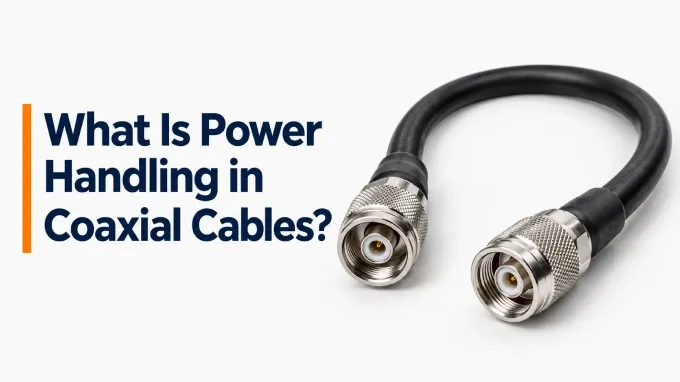
Power handling in a coaxial cable is the maximum RF power it can transmit without overheating or suffering electrical breakdown, under specified operating conditions. It is usually expressed in watts or kilowatts. Two separate limits determine that capability: peak power and average power.
Peak RF power is the highest power in the signal envelope. Average power is the power averaged over time, while CW power is applied continuously.
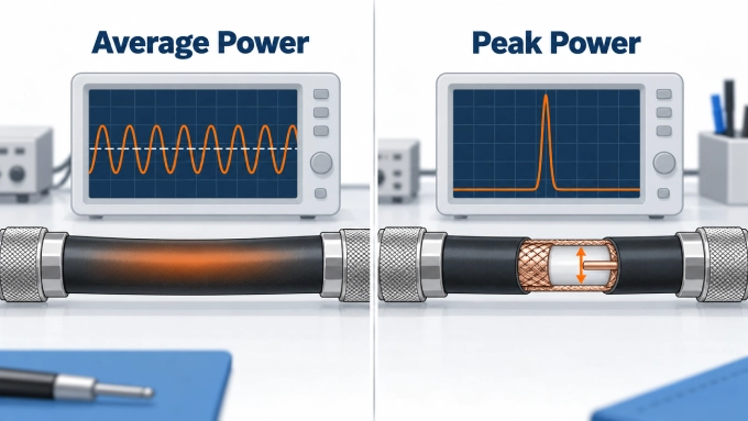
Here is a quick overview:
What is RF Average Power?
Average and CW power handling are primarily thermal specifications. A portion of the RF energy transmitted through a real coaxial cable is lost in the conductors and dielectric. That energy becomes heat. The average-power rating is established so that the resulting cable temperature remains within the allowable range of its materials under the stated conditions.
What is RF Peak Power?
Peak power, by contrast, is primarily associated with voltage and electric-field capability. A sufficiently high RF voltage can exceed the permitted electric field within the dielectric or at another part of the coaxial structure. Peak capability is therefore closely related to dimensions, dielectric strength, voltage rating, and characteristic impedance.
What Determines Coaxial Cable Power Handling?
Frequency, construction, VSWR, temperature, and other conditions can therefore affect the applicable rating. Change one of those variables and the applicable rating can change as well. Power ratings should therefore be read as conditional specifications rather than as absolute properties of the cable.
1. Operating Frequency
Coaxial cable power ratings generally decrease as frequency increases. Higher frequencies produce greater conductor and dielectric losses, converting more RF energy into heat. A rating should therefore always be stated at a specific frequency or provided as a power-versus-frequency curve.
2. Cable Diameter
Larger coaxial cables generally receive higher power ratings. Their larger conductors have lower resistance, greater conductor spacing improves voltage withstand, and the larger outer surface provides more area for heat dissipation. For this reason, cable diameter is an important consideration when specifying custom RF cable assemblies for high-power applications.
Diameter is not the only consideration, however. Two cables of similar size can have substantially different ratings because of their conductor and dielectric construction.
3. Conductor Material and Construction
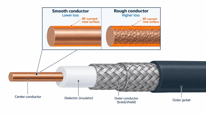
The center and outer conductors create resistive loss. Their diameter, conductivity, plating, surface condition, and construction therefore affect the cable’s thermal rating.
At higher frequencies, skin effect concentrates RF current near the conductor surfaces. This increases effective resistance and conductor loss. Smooth copper or silver-plated conductors generally produce less high-frequency loss than rougher or less conductive surfaces.
4. Dielectric Material and Construction
Dielectric loss converts part of the RF signal into heat inside the cable. Materials with a lower loss tangent generally support higher average power because they generate less heat.
The dielectric’s thermal conductivity and maximum operating temperature also influence the average rating. Its dielectric strength and the spacing between conductors affect peak-voltage withstand. Solid, foamed, microporous, and air-spaced dielectrics can therefore receive different power ratings even in cables of similar diameter.
5. Characteristic Impedance
Characteristic impedance affects the voltage and current associated with a given power level. For the same power, a higher-impedance cable carries higher voltage and lower current. A lower-impedance cable carries lower voltage and higher current.
For air-filled coax with fixed outer dimensions, maximum theoretical power occurs near 30 Ω, while minimum attenuation occurs near 77 Ω. The standard 50 Ω impedance provides a practical compromise between power handling and loss. In real cables, construction and system matching matter more than impedance alone.
6. VSWR and Reflected Power
Published power ratings commonly assume a matched or near-matched load. When the load impedance does not match the cable, some power reflects toward the source.
The forward and reflected waves create higher voltage and current points along the cable. These peaks can increase heating or electrical stress, so manufacturers may provide a VSWR correction factor for their published rating.
7. Connectors and Terminations
A bulk coaxial cable rating does not automatically apply to a finished cable assembly. Connectors, adapters, feedthroughs, terminations, and cable-to-connector transitions have their own frequency, average-power, and peak-voltage ratings.
The complete assembly cannot be rated above its lowest-rated component. Connector contact size, dielectric geometry, mating condition, and termination workmanship can all affect the final RF cable assembly power handling specification.
8. Temperature and Cooling
CW power ratings are normally published at a specified ambient temperature. Higher ambient temperatures reduce the permitted temperature rise inside the cable and therefore reduce its usable rating.
Cooling conditions also matter. A cable installed in open air may dissipate heat more effectively than one placed in a sealed enclosure or cable bundle. Manufacturers may provide temperature correction factors when the application differs from the reference conditions.
9. Altitude and Pressure
Power ratings are often specified at sea level. Lower air density reduces convective cooling and changes voltage-breakdown behavior, so high-altitude applications may require additional derating.
Altitude correction factors are manufacturer-specific. Vacuum applications require separate consideration because convection is unavailable and the electrical breakdown mechanisms differ from those at normal atmospheric pressure.
10. Cable Length and Installation Geometry
Cable length affects total RF signal loss and the amount of power dissipated along the transmission path. However, a longer cable does not automatically have a lower power-handling rating, because heat is distributed along the cable and dissipated through convection, radiation, and conduction.
Installation conditions also matter. A cable routed through a sealed enclosure or bundled tightly with other cables may dissipate heat less effectively than one installed in open air. Connector losses and heat transfer through mounting hardware can further influence the temperature of the complete assembly.
When selecting a cable for high-power applications, use the manufacturer's power ratings and correction data that match the actual installation and operating conditions.
Coaxial Cable Power Handling Formula
No single formula establishes a coaxial cable’s complete power rating. The following relationships connect RF power with voltage and pulse duty cycle; the thermal limit still depends on the cable’s construction and operating conditions.
For a matched coaxial line carrying a sinusoidal signal:
Here, is power in watts, is characteristic impedance in ohms, and and are RMS and peak voltage in volts. Peak voltage means the carrier’s amplitude, not its peak-to-peak voltage. Use the applicable RF operating-voltage limit when checking voltage capability; a dielectric-withstand test voltage is a different specification.
For rectangular RF pulses with constant power during each pulse and negligible power between pulses:
where is duty cycle, calculated as pulse width divided by pulse repetition period.
For example, 1,000 W pulses at a 10% duty cycle produce 100 W average power. The cable must meet both the average-power requirement and the peak-power requirement under the specified operating conditions.
How to Determine the Maximum RF Power for a Coaxial Cable Assembly
Use the following process to select the applicable rating for a custom RF cable assembly:
Identify the exact cable part number. Generic names such as RG58 can cover different constructions and ratings.
Find the rating at the operating frequency. Do not use a value specified at a lower frequency unless the manufacturer permits it.
Identify the power type. Determine whether the application uses CW, average, peak, or pulsed power.
Check both average and peak requirements. Pulsed operation can remain below the average rating while exceeding the peak-voltage limit.
Review the reference conditions. Confirm the ambient temperature, altitude, cooling condition, and assumed VSWR behind the published rating.
Apply the manufacturer’s correction factors. Use the supplied temperature, altitude, and VSWR derating data where applicable.
Check every assembly component. Review the connector, adapter, feedthrough, and termination ratings at the operating frequency.
Use the lowest applicable rating. The final limit is set by the lowest-rated cable or component after derating.
Include an engineering margin. Do not operate continuously at the absolute published maximum without accounting for tolerances and expected operating variation.
A meaningful coaxial cable power rating therefore belongs to a specific cable, frequency, power type, and set of reference conditions. The maximum safe rating for a finished assembly is the lowest applicable value after all required corrections.
Why Two Similar Coaxial Cables Can Have Different Power Ratings
Two coaxial cables can share the same 50-ohm impedance, similar outside diameter, and similar frequency range yet still carry different RF power ratings.
The reason is that the rating reflects several electrical and material properties simultaneously.
This is why terms such as high power coaxial cable or low-loss coax describe useful categories but cannot replace actual power data.
A low-loss cable often has favorable average-power capability because lower attenuation means less RF energy is dissipated internally. However, low attenuation does not automatically establish its voltage rating, temperature rating, or connector assembly capability.
FAQ
Discussion (0)
Be the first to comment.