Differences Between Fixed and Variable RF Attenuators
Compare fixed and variable RF attenuators by accuracy, insertion loss, repeatability, power handling, and control. Learn which design fits your RF system.

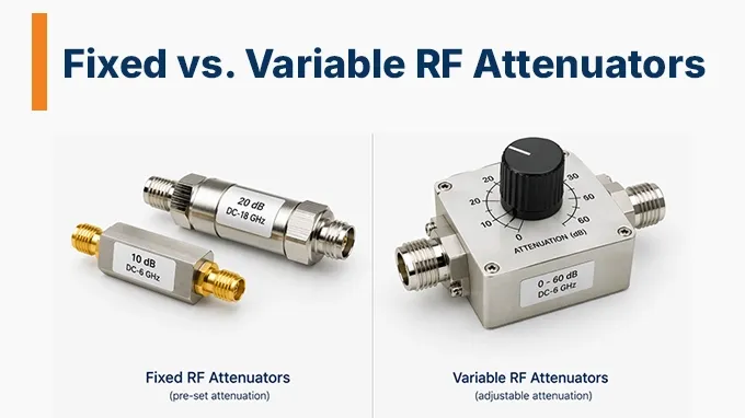
A fixed attenuator provides one nominal attenuation value. A variable attenuator allows that value to change manually or electronically, through discrete settings or a continuously adjustable range.
Choose fixed attenuation when one installed loss value meets the system's needs. Choose variable attenuation when the loss must be adjusted during setup, testing, or operation. The practical trade-off is adjustment flexibility versus control and characterization effort; accuracy and power handling must be compared for the specific designs.
Decision factor | Fixed RF Attenuator | Variable RF Attenuator |
Required loss | One nominal value | Adjustable values |
Changing the setting | Replace the pad | Adjust the control |
Software control | External switching needed | Programmable models |
Control hardware | None for a passive pad | Manual control or circuitry |
Characterization | One installed setting | Each setting used |
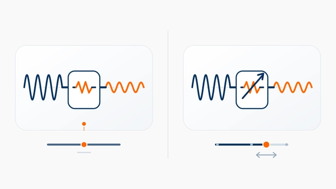
Fixed vs. Variable RF Attenuators: Adjustment and Control
A fixed RF attenuator establishes a specified loss through a passive network, commonly using resistive elements. Because its attenuation state does not change, there is no need for switching logic, control-voltage calibration, or transition timing.
Manual and Electronic Adjustment
Manual step or continuously adjustable attenuators suit occasional setup changes when an operator can reach the control. They provide adjustment without requiring a software interface.
A digital step attenuator (DSA) selects discrete attenuation states using logic commands. It suits programmed test points and attenuation sweeps. A voltage-variable attenuator (VVA) changes attenuation through an analog control voltage and suits continuous level adjustment.
For automatic level control, the attenuator also needs a detector and feedback controller, or another suitable source of control commands. A variable attenuator does not sense and regulate the output by itself.
Switching and Settling Time
A fixed attenuator has no setting transitions. An electronically controlled variable design needs time to accept a command and settle to the new RF level. In an automated test, taking the measurement too early can produce an incorrect result.
For fast control loops, settling time and transient behavior may be more important than nominal attenuation resolution.
Use the settling-time specification at the required accuracy, rather than switching time alone, to decide when the next measurement or control action can begin.
Fixed vs. Variable RF Attenuators: Total Insertion Loss
For a fixed attenuator, total insertion loss is its nominal attenuation plus the actual deviation under the operating conditions. For a variable device, distinguish total path loss from attenuation specified relative to a reference state.
An important distinction is that a variable attenuator's nominal 0 dB state is not necessarily lossless.
In a hypothetical DSA with 1.0 dB reference-state insertion loss and 10 dB selected relative attenuation, the total nominal loss is approximately:
This assumes that the selected attenuation is specified relative to the reference state and excludes additional state and frequency errors.
The minimum-state loss also sets a floor: a variable device with 1.0 dB minimum loss cannot provide a total loss of 0.5 dB. Establish the lowest loss the system needs before selecting the adjustment range.
How Do Fixed and Variable RF Attenuators Compare in Performance?
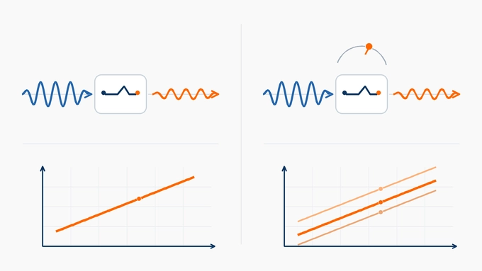
Compare both designs over the same frequency band and operating conditions. A fixed attenuator needs to meet the requirements at its installed value; a variable attenuator needs to meet them at every setting the system will use.
Attenuation Accuracy
Attenuation accuracy describes the difference between actual and specified attenuation.
For a fixed attenuator, the relevant measurement is its actual insertion loss against its nominal value.
For a variable attenuator, engineers may need to evaluate both reference-state loss and relative attenuation error for each selected state.
Consider a hypothetical digital attenuator specified with:
Reference-state insertion loss: 1.0 dB
Selected relative attenuation: 20.0 dB
Relative attenuation error: ±0.4 dB
Ignoring uncertainty in the reference-state loss, the resulting total loss would range from approximately 20.6 to 21.4 dB.
If the required total loss is 20.0 dB ±0.2 dB, this nominal 20 dB setting fails the requirement. A different setting may correct the nominal offset, but its remaining error still has to fit the tolerance.
When guaranteed specifications do not meet the allowed error, characterize the path and apply corrections where practical, or select another device. Either fixed or variable attenuation may require calibration; corrections do not remove drift or repeatability limits.
Frequency Flatness
Frequency flatness describes how attenuation varies across the operating band.
A fixed attenuator can stay at one nominal setting while its actual loss changes with frequency. For a variable attenuator, the frequency response can also change with the selected state.
At microwave frequencies, parasitic capacitance, inductance, package transitions, and interconnect geometry influence attenuation and matching.
For a wideband path, compare loss across the full band, including the band edges and any specified worst-case points. A fixed pad needs one acceptable response; a variable device needs acceptable responses for the settings used. Frequency-dependent calibration is useful only if the system can apply the resulting corrections.
A wide nominal frequency range does not mean every specification remains constant throughout that range.
Step Resolution
Step resolution is the smallest nominal attenuation increment that a digital or mechanical step attenuator can select. A fixed attenuator has no adjustable step size; finer variable steps allow closer selection of a target level but do not guarantee better accuracy.
For example, a hypothetical step attenuator might have the following specifications:
Parameter | Value |
Step resolution | 1 dB |
Attenuation accuracy | ±0.3 dB |
Switching repeatability | ±0.03 dB |
A 1 dB step resolution means the available nominal settings are separated by 1 dB. For a target halfway between two ideal settings, the nearest selection is 0.5 dB away. Without another adjustment mechanism, this device cannot guarantee arbitrary targets within ±0.2 dB, even before attenuation error is included.
Repeatability
Repeatability describes how closely the attenuator reproduces the same attenuation when the same setting is selected repeatedly under consistent operating and measurement conditions.
A switching repeatability of ±0.03 dB means that repeated selections of the same setting reproduce attenuation within the stated repeatability tolerance.
Therefore, an attenuator can return consistently to nearly the same value while remaining offset from its nominal attenuation. High repeatability does not necessarily mean high absolute accuracy, and finer step resolution does not guarantee either.
Fixed attenuators do not have setting-selection repeatability requirements because their attenuation is not switched between states. However, their actual attenuation can still vary with frequency, temperature, and aging.
For repeated measurement sequences, ask whether the same command returns the RF level within the test's permitted variation. A correction for nominal attenuation error is useful only while that setting remains sufficiently repeatable.
Impedance Matching
A well-characterized attenuation pad can reduce sensitivity to impedance mismatches and improve measurement consistency. For a fixed pad, assess the installed path; for a variable device, compare input and output return loss across the settings used.
If changing attenuation also changes the match, the measured level can shift through mismatch effects as well as the intended attenuation. This matters when the source or load is poorly matched, so compare performance in the intended system impedance and include mismatch uncertainty in precision measurements.
Phase Response
Variable attenuators can introduce state-dependent phase shifts. A fixed attenuator also has phase delay, but it does not add a change associated with selecting another attenuation state.
These effects matter in phased-array systems, coherent receivers, vector measurements, and other applications where amplitude and phase must remain controlled.
If attenuation must change while phase stays controlled, use the permitted phase variation to screen the required settings. An amplitude-only calibration does not establish acceptable phase behavior.
Linearity
Semiconductor variable attenuators may also exhibit nonlinear distortion. Parameters such as input P1dB and IIP3 can change with attenuation settings.
Fixed resistive attenuators are generally highly linear within their operating limits, but their behavior is still constrained by power, heating, and physical construction.
For a distortion-sensitive path, compare compression and intermodulation performance at the maximum operating input level and the settings used. A device can remain below its damage limit while already introducing unacceptable distortion.
Fixed vs. Variable RF Attenuators: Power Handling
Power handling can eliminate an otherwise suitable architecture.
Continuous and Peak Input Power
An attenuator's power rating must be evaluated against the maximum RF power reaching its input.
For a well-matched, dissipative 20 dB attenuator receiving 1 W:
Approximately 0.99 W is dissipated internally, assuming negligible reflected power.
For a constant-loss high-power path, a fixed pad with adequate thermal capacity avoids the need for a power-rated switching mechanism. A variable solution must meet the input-power limits of every state used.
Power ratings also require attention to frequency, ambient or case temperature, cooling, duty cycle, and any specified derating.
A suitable average-power rating does not establish that a device can tolerate the signal's peaks. Use both average and peak input limits when selecting either type.
Switching Under RF Power
Hot-switching ratings are particularly important: an attenuator may tolerate a given input power while holding one state but have a different permitted power level during a state transition.
This transition limit is an additional selection constraint for variable attenuators. If the required RF level exceeds the hot-switching rating, reduce or mute the RF during changes where the system allows it, or choose a device rated for the transition.
How to Choose Fixed, Variable, or Combined Attenuation
A useful selection process begins with the required signal-level behavior rather than the available attenuator technologies.
1. Decide Whether One Fixed Value Works
Define the input-power range and the permitted output-power range at the attenuation stage. A changing input does not automatically require variable attenuation: one fixed value is sufficient if it keeps the full input range within the allowed output range.
Consider a hypothetical RF test system operating from 1 to 6 GHz with +10 dBm at the attenuator input.
The device under test requires −2 dBm ±0.5 dB.
The nominal total attenuation requirement is:
A suitably specified 12 dB fixed attenuator is a reasonable starting point. The source variation, path-loss error, and measurement uncertainty must together fit the ±0.5 dB output allowance across the required band.
If attenuation only needs adjustment during commissioning, compare a manual variable device with selecting a fixed pad after setup. Routine remote adjustment is unnecessary unless the system actually needs it.
2. Determine the Required Adjustment Span
Now suppose the input may vary between +4 and +16 dBm while the DUT must remain near −2 dBm.
The nominal total-attenuation targets are:
A fixed 12 dB attenuator cannot maintain the required output level across that range without additional gain or attenuation control elsewhere.
A variable attenuator can cover the nominal 6 to 18 dB total-loss targets, a 12 dB adjustment span. For programmed input changes, command the corresponding settings; for unknown changes, provide sensing and a controller to track them.
3. Choose the Control and Reachable Settings
Use a manual control for accessible setup adjustments, a programmable step attenuator for defined level sequences, or a VVA when continuous analog adjustment is required. Choose step size and settling time to fit the output tolerance and update rate.
Assume the hypothetical DSA has 1.0 dB reference-state insertion loss at the measurement frequency and operating conditions.
A nominal 11 dB relative attenuation state would then produce approximately:
At this frequency, the nominal 6 to 18 dB total-loss targets would require relative settings from 5 to 17 dB. The available step size and remaining attenuation error must fit within the ±0.5 dB output-level tolerance. Repeat this assessment across the required frequency band.
4. Consider Fixed Attenuation Plus Adjustable Trim
A fixed pad can supply baseline loss while a variable element provides the remaining adjustment. At the same illustrative frequency and conditions, a 5 dB fixed pad followed by a DSA with 1 dB reference loss and 0 to 12 dB relative adjustment would nominally cover 6 to 18 dB total loss.
This combination is useful when baseline loss is always needed and adjustment is confined to a smaller span. It also raises the minimum loss: verify the pad's dissipation and the RF power reaching the variable device, and include both devices' errors.
Use the following constraints to reject unsuitable candidates rather than treating every specification as equally decisive:
Constraint | Reject the candidate if... |
Loss range | Required total loss falls outside its available range. |
Error budget | Attenuation error and other path uncertainties exceed the output allowance. |
Resolution | Available settings cannot reach the target closely enough. |
Input power | Any used state exceeds the average or peak input rating. |
Switching | Hot-switching limits, settling, or transients exceed system limits. |
Matching | Mismatch uncertainty exceeds the measurement allowance. |
Phase | Phase variation across required states exceeds the allowed error. |
Linearity | Compression or intermodulation exceeds the permitted distortion. |
Integration | Required supplies, control hardware, or cooling cannot be provided. |
For precision applications, use calibration data measured at representative frequencies and temperatures rather than assuming nominal values are exact.
The final choice of RF attenuator architecture should follow the system's allowable error and operating constraints, not a general preference for fixed or variable designs.
FAQ
Discussion (0)
Be the first to comment.