How Do Coaxial Cables Work? RF Signals & Data Transmission Explained

A coaxial cable works by transmitting an electrical or radio-frequency (RF) signal that represents digital information. A transmitter encodes digital data into a changing electrical or RF signal, and the center conductor and surrounding shield of the coax cable guide the signal as an electromagnetic wave, while the receiving device demodulates and decodes it back into usable data.
In specialized systems, custom RF cable assemblies may be used to connect, route, or adapt these signals between devices while maintaining the required impedance and signal integrity.
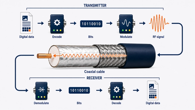
The basic process of how coax RF cables work is:
The source produces the information: A source device creates digital data such as internet data, video, audio, or measurements as bits containing binary ones and zeros. Analog systems instead produce a continuously varying signal.
A transmitter encodes the data: The transmitter organizes digital data into a format the receiving device understands. It may group bits into frames, add synchronization information, and include forward error-correction data. Error-correction data allows the receiver to identify or repair possible errors.
The transmitter then converts the data into an electrical waveform: The transmitter device or modem converts those bits into an electrical signal. The device represents the binary ones and zeros using controlled changes in an electrical waveform and sends it through the coax cable.
The signal travels through the cable: The electrical waveform travels at a large fraction of the speed of light. As it travels, attenuation, noise, and impedance discontinuities can weaken or distort it.
A receiver detects and decodes the signal: The receiving device detects the incoming waveform. If several signals occupy the cable, a tuner or filter first selects the required frequency range. The receiver then demodulates the signal, identifies the transmitted symbols, and converts them back into bits.
The original digital data is reconstructed: Finally, decoding and error-correction processes in the receiver reconstruct the original internet data, video, audio, or measurement information.
In short:
Digital data → transmitter → electrical/RF signal → coaxial cable → receiver → digital data
What Actually Travels Through the Coaxial Cable?
The most useful distinction here is between the data and the signal carrying that data. The data consists of digital information. The coax cable carries an electrical/RF waveform that has been encoded with that information.
Depending on the communication system, information may be encoded by changing characteristics such as:
Amplitude: the strength of the signal
Phase: the position of the waveform within its cycle
Frequency: how quickly the waveform oscillates
Combinations of these properties: used by more advanced modulation methods
These controlled changes allow the receiving equipment to determine which digital information was transmitted.
The Four-Layer Structure of RF Coaxial Cables
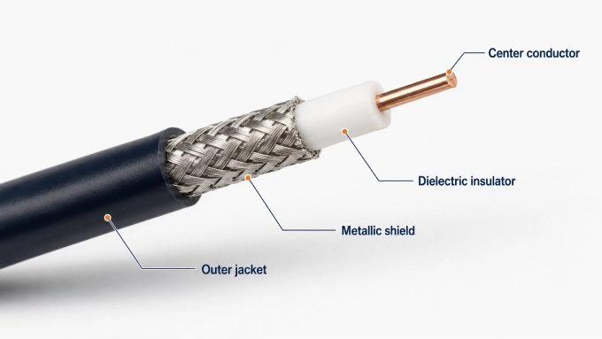
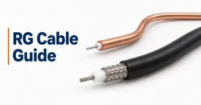
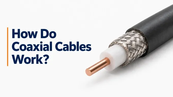
An RF coaxial cable is built in concentric layers, with the signal conductor running through the center and a metallic shield surrounding it. This structure helps the cable carry high-frequency signals while limiting interference and signal leakage.
The four main layers are:
Center conductor
Dielectric insulator
Metallic shield
Outer jacket
1. Center Conductor
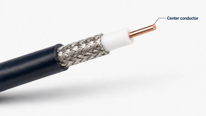
The center conductor is usually made of copper or copper-clad metal and carries the changing electrical signal.
Its job is to conduct the RF or data signal, provide a consistent path for signal transmission, and work with the outer shield to form the coaxial transmission line.
The size and material of the conductor can affect resistance, attenuation, and the frequencies the cable can handle efficiently.
2. Dielectric Insulator
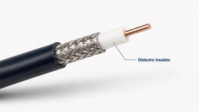
The dielectric is the insulating material between the center conductor and the metallic shield.
It serves several important functions. It keeps the two conductors electrically separated and maintains a fixed spacing between them. The insulator also helps determine the cable’s characteristic impedance and influences how quickly the signal propagates through the cable.
Because the spacing must remain consistent, damage or crushing can change the cable’s electrical properties and affect signal quality.
3. Metallic Shield
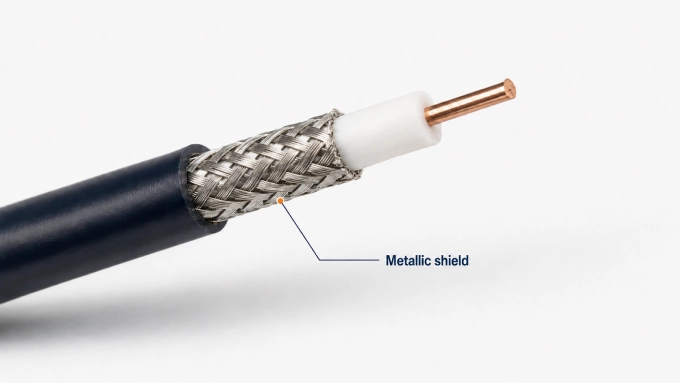
The metallic shield surrounds the dielectric and may consist of foil, braided metal, or a combination of both.
It has two main roles:
acts as the outer conductor and return path for the signal;
protects the cable from electromagnetic interference (EMI) and radio-frequency interference (RFI).
The shield also helps keep the transmitted RF energy contained within the cable instead of allowing it to radiate outward. Better shielding is especially useful in environments with strong electrical noise or many nearby signal sources.
4. Outer Jacket
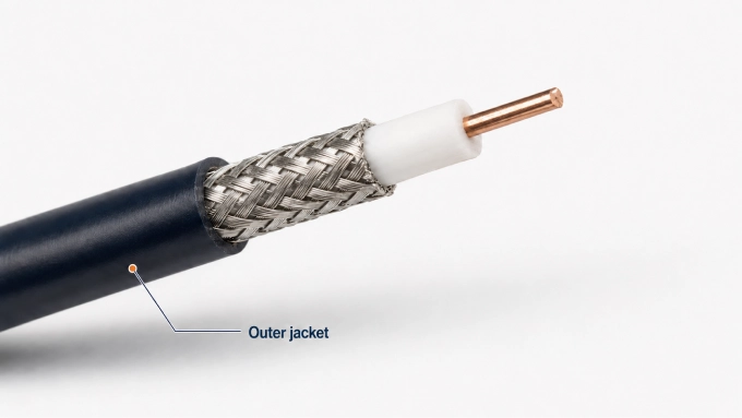
The outer jacket is the cable’s protective layer. It does not carry the signal, but it protects the internal structure from physical and environmental damage. Depending on the cable type, the jacket may provide resistance to abrasion, moisture, heat, sunlight, and chemicals.
Keeping the internal layers intact is important because changes in conductor spacing or shield continuity can increase attenuation, reflections, or interference.
Why This Structure Matters
The RF coaxial design keeps the center conductor and shield at a controlled distance from each other along the length of the cable.
That helps maintain:
stable characteristic impedance;
predictable high-frequency signal behavior;
lower susceptibility to outside interference;
better signal containment.
In other words, coax works well not simply because it uses copper, but because its layered geometry creates a controlled path for RF signal transmission.
How Is Data Sent Through a Coaxial Cable?
A coaxial cable carries internet data by transmitting an RF electrical signal that represents digital information. The transmitting equipment encodes the data into a changing RF waveform, while the receiving device demodulates and decodes it back into usable data. Cable broadband uses DOCSIS (Data Over Cable Service Interface Specification) to define how cable modems and the provider’s equipment communicate.
How Cable Internet Reaches Your Modem
Cable internet usually does not travel over coax cables for the entire journey. Most cable providers use a hybrid fiber-coaxial (HFC) network. Fiber carries data across most of the provider’s network, while coaxial cable handles the final portion between a neighborhood fiber node and individual buildings.
The path looks like this:
Internet → provider’s CMTS → fiber network → fiber node → coaxial cable → cable modem → router or connected device
Downstream data travels from the internet toward the user through the following process:
The CMTS receives the downstream data: The cable modem termination system (CMTS) connects the cable network to the provider’s internet infrastructure. It receives data intended for cable modems on the network.
The signal travels through the fiber network: The downstream data travels optically from the provider’s network toward a fiber node serving a neighborhood or local area. Depending on the network architecture, the fiber link carries an optical representation of the RF waveform or digital data from which the node generates that waveform.
The fiber node supplies the RF signal: In traditional HFC networks, the optical signal is converted into an RF electrical signal suitable for transmission over coaxial cable. In Remote PHY networks, the node receives digital data over fiber and performs the downstream RF modulation locally.
The coaxial network carries the signal to the building: The downstream RF signal travels through cables, taps, and splitters to the cable modem.
The cable modem recovers the data: The modem selects the downstream channels carrying internet data, demodulates the RF signal, and identifies the transmitted symbols. It then decodes the data, applies error correction where possible, and passes the recovered internet traffic to a router or connected device.
For uploads, the data travels in the opposite direction. The modem takes digital data from your device, converts it into an appropriate upstream RF signal, and sends it back through the coaxial network. The provider schedules upstream transmission opportunities so that multiple modems can share the available capacity.
How Can One Coaxial Cable Carry So Much Data?
One cable can carry substantial amounts of data because communication equipment can use multiple frequency channels and encode multiple bits in each transmitted symbol.
A coaxial cable can carry signals across a broad frequency spectrum. Communication systems divide that spectrum into smaller frequency ranges, or channels, and use them for different streams of information.
In conventional frequency-separated cable networks, several channels can therefore travel through the cable at the same time:
Internet download data occupies downstream channels.
Internet upload data uses upstream channels in a separate frequency band.
Television programming may occupy additional designated RF channels.
Their electrical waveforms combine and propagate simultaneously. Receiving equipment separates the required channels by frequency. This technique is called frequency-division multiplexing (FDM).
Separate upstream and downstream bands are not universal: Full Duplex DOCSIS can reuse part of the spectrum for both directions simultaneously.
Modulation Packs More Information Into Each Signal
Using more frequency channels is only part of the story. Communication systems can also increase capacity by packing more information into each transmitted symbol.
A symbol is a particular signal state that the receiver can recognize. Instead of using only two possible states to represent a single 0 or 1, higher-order modulation selects each symbol from a larger set of possible states. Each state represents a particular group of bits.
For example:
Possible signal states | Bits represented per symbol |
2 | 1 bit |
4 | 2 bits |
16 | 4 bits |
64 | 6 bits |
256 | 8 bits |
One common technique is QAM (Quadrature Amplitude Modulation). QAM encodes information by varying the amplitude and phase of a carrier signal.
A 256-QAM system, for example, has 256 recognizable signal states. Because 2^8 = 256, each symbol can represent 8 bits. This means higher-order modulation can transmit more information without requiring one separate electrical pulse for every bit. These are encoded bits; error-correction and protocol overhead reduce the proportion available for the user’s internet data.
DOCSIS 3.1 also uses orthogonal frequency-division multiplexing (OFDM) downstream and orthogonal frequency-division multiple access (OFDMA) upstream. These techniques use many closely spaced, orthogonal subcarriers, with QAM applied to individual subcarriers.
Higher-order QAM requires sufficient signal quality for the receiver to distinguish closely spaced signal states. More available states can increase capacity, but attenuation, interference, and distortion can limit the modulation order a connection can reliably support.
What Affects Coaxial RF Cable Data Transmission Quality?
Coaxial cable can carry high-frequency data reliably, but signal quality depends on the cable, installation, distance, and surrounding electrical conditions. If too much signal is lost or distorted, the receiver may struggle to decode the data correctly.
Here are the main factors:
1. Cable Length and Attenuation
As a signal travels through the cable, it gradually loses strength. This is called attenuation, and it is usually measured in decibels (dB).
Signal loss generally increases when:
the cable run is longer;
the signal frequency is higher;
the cable is thinner or lower quality;
the cable is damaged or poorly installed.
This is why there is no single maximum distance that applies to every coaxial connection. Performance depends on the cable type, frequency range, equipment, and acceptable signal level.
2. Impedance and Signal Reflections
Coaxial systems are designed to maintain a specific characteristic impedance, most commonly:
75 ohms for cable television and broadband;
50 ohms for many radio-frequency and communications systems.
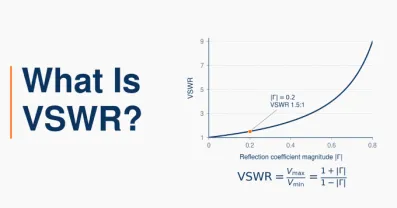
When the cable, connector, or device does not match the required impedance, part of the signal can reflect back toward the transmitter instead of continuing forward.
These reflections can distort the waveform and make the transmitted data harder to recover. Poor connectors, damaged cable, sharp bends, and incorrect components can all contribute to impedance problems.
3. Shielding and Interference
One of the main advantages of these cables is their metallic shield, which helps protect the signal from electromagnetic interference (EMI) and radio-frequency interference. Damaged shielding, loose connectors, or poor-quality terminations can allow unwanted noise to enter the cable.
Sources of interference may include:
electrical equipment;
radio transmitters;
poorly shielded cables;
damaged connectors;
nearby power wiring.
More interference means the receiver has a harder time distinguishing the intended signal from background noise.
4. Connectors and Splitters
Even a good RF cable can perform poorly if the connectors are badly installed.
Loose, corroded, or poorly fitted connectors may cause:
extra signal loss;
impedance mismatch;
reflections;
noise entering the cable.
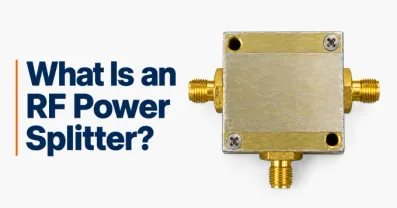
Splitters also reduce signal strength because the incoming signal is divided between multiple outputs. Each splitter introduces some insertion loss, so using too many splitters can weaken the signal before it reaches the modem, television, or receiver.
Signal-to-Noise Ratio Matters Most
Ultimately, reliable coaxial cable data transmission depends on whether the receiver can clearly distinguish the intended signal from unwanted noise.
This relationship is described by the signal-to-noise ratio (SNR).
A higher SNR means:
a cleaner signal;
fewer transmission errors;
more reliable decoding;
greater ability to use higher-capacity modulation.
A lower SNR can force the system to use more robust but less efficient signaling, reducing effective data capacity.
In practical terms, the best coaxial connection is not simply the shortest cable. It is a properly matched, well-shielded cable with good connectors, limited unnecessary splitters, and enough signal strength to maintain a clean transmission.
FAQ
Discussion (0)
Be the first to comment.