SMA Connector Dimensions: Charts, Drawings & Thread Size

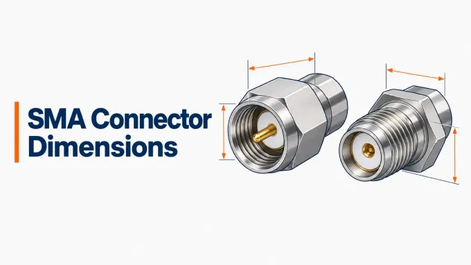
An SMA connector has standardized mating-interface dimensions, but its overall length, body diameter and mounting geometry depend on the connector’s construction.
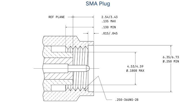
For a standard SMA interface, the jack has an external 1/4-36 UNS-2A thread, while the plug’s coupling nut has an internal 1/4-36 UNS-2B thread.
Thread specification | Millimeters | Inches / designation |
Thread designation | — | 1/4-36 UNS |
Nominal major diameter | 6.35 | 0.2500 |
Pitch: 36 threads per inch | 0.7056 | 0.02778 |
External mating-thread class | — | 2A |
Internal coupling-thread class | — | 2B |
The diameter above is the thread’s nominal size; actual thread dimensions must satisfy the specified class limits. Thread specifications follow Amphenol’s SMA plug and jack interface drawings.
Drawing legend:
Nominal: basic or designated size; not an acceptance limit.
MIN / MAX: lower and upper dimensional limits.
REF: an informational dimension, not an independently toleranced requirement.
Reference plane: the mating datum used for dimensions that explicitly reference it.
Unit conversions: rounded equivalents; preserve the source drawing’s limits and controlling units.
SMA Male Connector Dimensions in mm and Inches
Dimension | Millimeters | Inches |
Coupling-nut front bore diameter | 6.35–6.73 | 0.250–0.265 |
Outer-contact outside diameter | 4.53–4.59 | 0.1808 max. |
Reference plane to coupling-nut front face | 2.54–3.43 | 0.100–0.135 |
Dielectric-face recess behind reference plane | 0.00–0.25 | 0.000–0.010 |
Center-pin tip projection from reference plane | 1.91–2.54 | 0.075–0.100 |
Pin-shoulder recess behind reference plane | 0.00–0.25 | 0.000–0.010 |
Mating-pin diameter | 0.90–0.94 | 0.035–0.037 |
Pin-tip diameter | 0.00–0.38 | 0.000–0.015 |
Center-conductor diameter at dielectric face | 1.24–1.30 | 0.049–0.051 |
Rear thread-limit plane to coupling-nut front face | 3.302 min. | 0.130 min. |
Internal-thread entry setback from coupling-nut front face | 0.381–1.143 | 0.015–0.045 |
SMA Female Connector Dimensions in mm and Inches
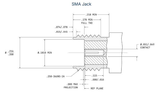
Dimension | Millimeters | Inches |
Outer-contact nose outside diameter | 5.28–5.49 | 0.208–0.216 |
Receiving-bore diameter | 4.5974 min. | 0.1810 min. |
Front face to reference plane | 1.88–1.98 | 0.074–0.078 |
Maximum projection beyond reference plane | 0.00 max. | 0.000 max. |
Front face to start of mating thread | 0.38–1.14 | 0.015–0.045 |
Socket front face to closed end of socket bore* | 2.921 | 0.115 |
Socket-face recess behind reference plane | 0.00–0.25 | 0.000–0.010 |
Front face to end of full thread | 4.32 min. | 0.170 min. |
Socket-contact outside diameter | 1.24–1.30 | 0.049–0.051 |
Front face to rear interface shoulder | 5.54 min. | 0.218 min. |
* The 0.115-inch socket-bore length is measured from the socket front face. The drawing does not attach a MIN or MAX qualifier to this dimension.
RP-SMA Male Connector Dimensions in mm and Inches
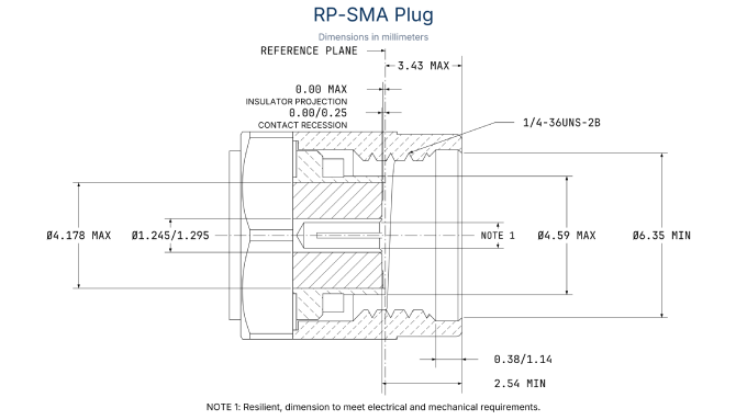
Dimension | Millimeters | Inches (approximate) |
Socket opening diameter | Functional requirement; no numerical limit | — |
Maximum insulator projection beyond reference plane | 0.00 max. | 0.00000 max. |
Socket-face recess behind reference plane | 0.00–0.25 | 0.00000–0.00984 |
Socket-contact outside diameter | 1.245–1.295 | 0.04902–0.05098 |
NOTE 1 identifies the resilient socket opening, whose dimensions must satisfy electrical and mechanical requirements. No numerical socket-opening diameter is specified.
RP-SMA Female Connector Dimensions in mm and Inches
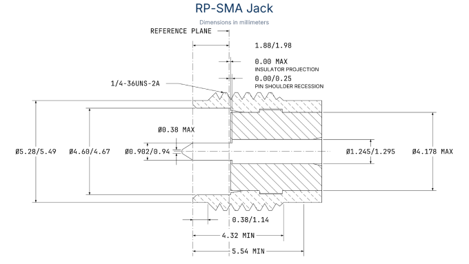
Dimension | Millimeters | Inches (approximate) |
Mating-pin diameter | 0.902–0.940 | 0.03551–0.03701 |
Pin-tip diameter | 0.38 max. | 0.01496 max. |
Pin-shoulder recess behind reference plane | 0.00–0.25 | 0.00000–0.00984 |
Maximum insulator projection beyond reference plane | 0.00 max. | 0.00000 max. |
Front face to reference plane | 1.88–1.98 | 0.07402–0.07795 |
Center-contact body diameter at dielectric | 1.245–1.295 | 0.04902–0.05098 |
What Dimensional Tolerances Matter for SMA Mating?
Identify the interface and drawing revision. Confirm SMA or RP-SMA, plug or jack, and the applicable drawing revision. Compare the connector against that interface’s dimensional limits.
Check the dimensions that control mating. Verify thread limits, center-contact diameter and projection/recess, outer-contact fit, and axial seating. These determine engagement and contact. Excessive contact diameter or projection can damage the mating connector.
Use the correct datum and inspection tools. Follow the drawing’s reference planes and measurement endpoints. Calipers can check accessible external dimensions; thread fit and contact position require suitable gauges. Use a connector gauge intended for the interface being inspected.
Incorrect seating or contact geometry can increase reflections and reduce measurement repeatability. Mechanical compatibility alone does not establish frequency range, return loss or power rating; verify the selected part’s electrical specifications. Amphenol explicitly qualifies its family specifications by connector construction.
For repeatedly used connectors, inspect threads, mating surfaces and contacts for wear or damage. Nominal dimensions and a published SMA connector mating cycles rating do not establish remaining service life.
Which Additional Dimensions Should You Check for PCB, Panel and Cable Design?
Use the selected part’s drawing to establish its installed position and attachment geometry relative to the PCB surface, panel face or assembly-length datum.
PCB installation: Footprint, attachment geometry, board-relative height, mating-axis centerline, projection and compatible board thickness where specified. For a PCB-mounted SMA female right angle connector, check both its footprint and installed envelope.
Panel installation: Specified cutout, mounting arrangement, usable mounting-thread length, panel-thickness allowance and nut/washer stack. For an SMA female bulkhead connector, verify its opening and mounting allowance.
Cable connection: Compatible cable, connector envelope, orientation, cable-exit direction and assembly-length reference points.
When specifying a custom rf cable assembly, provide the connector part numbers, compatible cable, allowable connector envelope and connector-to-connector length, including the measurement reference points.
Check clearance with the actual connector, mating partner, tool and layout. Allow room for both connector bodies, axial mating and unmating travel, coupling-nut rotation, finger or wrench access, and cable routing. Wrench access must accommodate the tool’s movement as well as its head. SMA connector torque is a specified tightening requirement; wrench size and available clearance do not determine it.
FAQ
Discussion (0)
Be the first to comment.