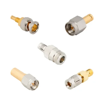
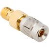
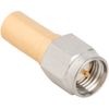
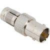

DIN 1.0/2.3 Adapter Specifications
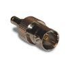
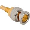
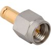
iPrece’s DIN 1.0/2.3 adapters connect to SMA, BNC and HD-BNC interfaces. Electrical ratings, materials and temperature limits vary by part number.
Electrical Specifications
Mating series | Impedance | Maximum frequency |
SMA | 50 Ω | 4 or 10 GHz |
BNC | 75 Ω | 2 GHz |
HD-BNC | 75 Ω | 3 GHz |
The 10 GHz rating applies to selected SMA models. Contact engineering for part-specific VSWR and insertion-loss specifications.
Mechanical Specifications and Materials
The range features straight, between-series adapters with DIN 1.0/2.3 plug or jack interfaces.
Parameter | Available specifications |
Panel mounting | Bulkhead options |
Body material | Brass / stainless steel / beryllium copper |
Body finish | Gold / nickel |
Contact material | Beryllium copper / brass |
Contact finish | Gold |
Insulator | PTFE |
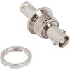
An isolated bulkhead option is available with DIN 1.0/2.3 jack and HD-BNC jack interfaces.
Operating Temperature
Adapter group | Operating temperature |
SMA, 4 GHz | −40 to +85 °C or −40 to +155 °C |
SMA, 10 GHz | −65 to +165 °C |
BNC and HD-BNC | −65 to +165 °C |
Check the selected part number for its exact temperature rating and material configuration.
How to Select the Right 1.0 2.3 Adapter
Start by identifying the two interfaces that must be connected. A DIN 1.0/2.3 adapter is a between-series transition, so both the 1.0/2.3 side and the mating connector on the opposite side must be specified correctly.
Before selecting a 1.0/2.3 RF adapter, verify:
Connector interface and gender: Identify the connector series and required plug or jack at both ends. Confirm the center-contact arrangement and mating dimensions.
System impedance: Choose a 50 Ω or 75 Ω configuration appropriate for the signal path. Do not assume that a mechanically compatible adapter provides the correct impedance.
Operating frequency: Verify the maximum rated frequency for the exact interface combination. The entire operating band must remain within the specified limits.
RF performance: Check VSWR or return loss and insertion loss at the relevant frequencies. Confirm any required measurement limits with the product documentation or quotation.
Mounting and clearance: Determine whether a straight adapter is suitable and whether a bulkhead configuration or electrical isolation is required.
Environmental requirements: Confirm the operating temperature, material construction, and any applicable environmental or compliance requirements.
A connector that physically mates with the equipment is not automatically suitable for the intended RF application. Confirm the documented performance of the complete adapter before installation.
DIN 1.0-2.3 Adapters and Configurations
DIN 1.0-2.3 adapters are used to transition between the compact 1.0/2.3 interface and another RF connector family. The right configuration depends on the interfaces, signal characteristics, and installation requirements.
DIN 1.0/2.3-to-SMA Adapters
A DIN 1.0/2.3-to-SMA adapter connects equipment using the 1.0/2.3 interface to equipment with an SMA port. These transitions are relevant to RF instrumentation, compact equipment, and test setups where a defined 50 Ω connection is required.
The rated frequency depends on the exact adapter design and gender combination. Selected configurations are rated up to 10 GHz, while other variants have lower specified limits. Verify the complete interface combination rather than applying one frequency rating to every 1.0/2.3-to-SMA adapter.
DIN 1.0/2.3-to-BNC Adapters
A DIN 1.0/2.3-to-BNC adapter provides a transition between the compact DIN interface and BNC equipment. Selected 75 Ω configurations are rated up to 2 GHz and may be appropriate for compatible broadcast, video, and instrumentation signal paths.
Check the impedance at both ends and the required frequency range. A BNC interface's mechanical fit does not establish that the adapter is suitable for every 50 Ω or 75 Ω application.
Straight and Bulkhead Configurations
Straight adapters are suitable when the connected ports align directly and enough clearance is available for the adapter and its mating interfaces. Selected bulkhead adapters allow the connection to pass through and be secured to a panel or equipment enclosure.
The available DIN 1.0-2.3 adapter configurations should not be assumed to include every possible body geometry. If the installation requires an angled body, a particular panel thickness, or a specific isolation arrangement, confirm the supported configuration before specifying the part.
DIN 1.0/2.3 RF Adapter Applications
DIN 1.0/2.3 adapters connect equipment with different coaxial interfaces, supporting signal routing in broadcast video, RF test systems, telecommunications networks, and industrial instrumentation.
Broadcast Video Systems
Broadcast systems use 75 Ω adapters to connect DIN 1.0/2.3 equipment ports with BNC or HD-BNC cabling. These transitions serve video routing racks, studio installations and production equipment.
RF Test and Measurement
DIN 1.0/2.3-to-SMA adapters connect equipment under test to SMA test cables and instruments. They provide interface transitions during RF characterization, bench troubleshooting and production testing of components and assemblies.
Telecom Infrastructure
In telecom racks and communications equipment, these adapters link DIN 1.0/2.3 connections with SMA cabling. They provide RF interconnections between modules and connect equipment to test leads during maintenance.
Industrial and Embedded Equipment
Within industrial instruments and embedded systems, these adapters connect DIN 1.0/2.3 interfaces to cabling or adjacent assemblies. Bulkhead versions provide connection points through equipment panels, linking internal coaxial connections with external cables.
Equipment Servicing and Connector Protection
Left attached to equipment ports, these adapters provide replaceable interfaces for repeated cable connections. Technicians can connect and disconnect leads during testing and servicing while reducing direct mating cycles on the original ports.
Technical Specifications and Ordering Requirements
Before requesting a quotation, define the complete interface and performance requirements of the application.
Connector combination: Specify the DIN 1.0/2.3 interface and the connector family required at the opposite end.
Gender: Identify the plug or jack arrangement at both ends.
Impedance and frequency: Provide the required 50 Ω or 75 Ω system impedance and the full operating frequency range.
RF performance: State any required VSWR, return-loss, or insertion-loss limits.
Mounting and isolation: Identify bulkhead installation needs, panel constraints, and any required electrical isolation.
Materials and environment: Specify operating-temperature limits, construction requirements, and applicable environmental constraints.
Testing and documentation: State whether VNA measurement data, S-parameter reports, traceability records, or material-compliance documentation are required.
These details help distinguish an adapter that simply fits the interfaces from one that meets the application's electrical, mechanical, and environmental requirements.
Quality and Standards
iPrece identifies its DIN 1.0-2.3 adapter family as VNA-tested and states ISO 9001:2015 certification at the company level. For engineering approval, confirm the test scope and any product-specific requirements for the exact configuration.
RF verification: Confirm the tested frequency band, measured parameters, acceptance limits, and availability of test documentation.
Mechanical compatibility: Verify the mating interfaces, mounting geometry, and isolation arrangement against the product documentation.
Material compliance: Request the applicable declarations for the selected configuration where RoHS, REACH, PFAS, or other material requirements apply.
Standards and qualification: Identify any required interface or environmental standard in the RFQ. Compliance with an interface standard should not automatically be treated as qualification of the complete adapter or RF assembly.
Include any required qualification standard, environmental test profile, or measured RF test report in your RFQ for confirmation before ordering.