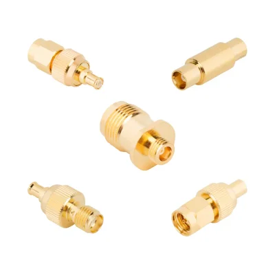
MCX Adapters in Straight and Right-Angle Designs
Control reflections and insertion loss in compact RF modules and densely populated panels. Source standard or custom MCX adapters with snap-on coupling in 50 Ω or 75 Ω coaxial RF designs. Options span in-series MCX-to-MCX connections and between-series transitions to SMA, TNC and BNC in straight, right-angle and bulkhead configurations. Selected models support operation up to 6 GHz, and specific bulkhead designs offer IP67 sealing.
Adapter TypeIn-Series / Between-Series
Impedance50 / 75 Ω
Frequency Max6 GHz
OrientationStraight / Right Angle
- Snap-on quick-connect design
- 3.6 mm micro-footprint
- IP67-rated bulkhead options
- 12G SDI optimized 75 Ω paths
Automotive & IoT modulesBroadband & Broadcast systemsTest & Instrumentation hardwareWLAN & GPS modulesWireless base stations
Fast Production OEM Direct 100% VNA Tested
20 Products
| Part / Description | Actions | body-material | frequency-max | vswr-max | impedance | insertion-loss | isolated |
|---|---|---|---|---|---|---|---|
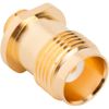
| Beryllium Copper | 6 GHz | Contact Engineering | 50 Ω | Contact Engineering | |||
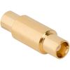
| Brass | 6 GHz | Contact Engineering | 50 Ω | Contact Engineering | |||
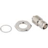
| Brass | 6 GHz | Contact Engineering | 50 Ω | Contact Engineering | |||
| Brass | 6 GHz | Contact Engineering | 50 Ω | Contact Engineering | |||
| Brass | 6 GHz | Contact Engineering | 50 Ω | Contact Engineering | |||
| Brass | 6 GHz | Contact Engineering | 50 Ω | Contact Engineering | |||
| Brass | 6 GHz | Contact Engineering | 50 Ω | Contact Engineering | |||
| Brass | 6 GHz | Contact Engineering | 50 Ω | Contact Engineering | |||
| Brass | 6 GHz | Contact Engineering | 50 Ω | Contact Engineering | |||
| Brass | 6 GHz | Contact Engineering | 50 Ω | Contact Engineering |

MCX Adapter FAQs
Does the 6 GHz rating apply to every MCX adapter? ↓
No. The maximum frequency depends on the exact adapter configuration. Selected MCX-to-MCX, MCX-to-SMA, MCX-to-TNC, and MCX-to-AFI models are specified up to 6 GHz, while the documented BNC-to-MCX configuration is rated up to 4 GHz. Always verify the product-specific frequency range.
Can an MCX adapter be used as a connector saver for test equipment? ↓
Yes, an inline MCX adapter can serve as a replaceable mating point to reduce wear on an instrument or equipment port during repeated connections. However, its suitability as a connector saver depends on the adapter's interface, mechanical condition, and applicable mating-cycle rating. Do not assume a cycle-life value unless it is documented for the selected model.
Are MCX, MMCX, and SMB adapters interchangeable? ↓
No. MCX, MMCX, and SMB are distinct connector interfaces. Although they use compact snap-on coupling mechanisms, their mating geometry and dimensions differ. MCX is approximately 3.6 mm in outer diameter and is larger than MMCX. Identify the exact connector series at both ends and use a suitable between-series adapter when a transition is required.
Are all MCX adapters suitable for outdoor or moisture-exposed installations? ↓
No. A standard snap-on MCX interface is not inherently sealed. IP67 protection is specified only for selected bulkhead adapter configurations. Verify the exact product rating, mating arrangement, panel interface, and sealing conditions for the complete installation.
Can a 50 Ω MCX adapter be used in a 75 Ω signal path? ↓
Not by default. A 50 Ω adapter connected to a 75 Ω system can introduce an impedance discontinuity and signal reflections. Check the impedance of the adapter, cable, and equipment ports. Use a configuration documented for the required system impedance unless the design explicitly accommodates the mismatch.
When should I choose an MCX adapter instead of an MCX coaxial cable assembly? ↓
Use a rigid MCX adapter when two compatible equipment ports can connect directly and the installation provides enough clearance. Choose an MCX cable assembly when the connection requires a defined separation distance, flexible routing, or strain relief. The cable assembly must be specified and evaluated as a complete RF path.
What information is needed to verify an MCX adapter for an RF module? ↓
Provide the MCX interface gender, opposite-end connector, nominal impedance, operating frequency range, mounting geometry, and available installation space. For demanding applications, also specify insertion-loss, VSWR or return-loss limits, environmental conditions, and any required VNA or S-parameter documentation.