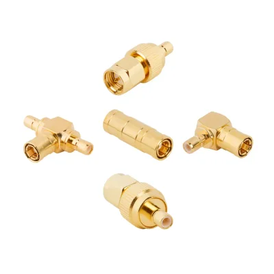

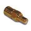
SMB Adapter Specifications
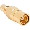
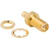
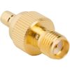
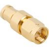
iPrece’s SMB adapters provide 50 Ω connections between SMB, SMA, SMC, and BNC interfaces. Most listed models operate up to 4 GHz, with selected SMA–SMB adapters rated to 10 GHz. Exact specifications depend on the selected model.
RF and Electrical Specifications
Parameter | Specification |
Nominal impedance | 50 Ω |
Representative VSWR limits* | Approx. 1.20:1–1.35:1, up to 4 GHz |
Reference insertion-loss limit* | Approx. 0.20 dB, up to 4 GHz |
* Starred electrical figures are published references for comparable two-port adapters. The inventory does not provide model-specific VSWR or insertion-loss ratings.
Connector Interfaces and Frequency Limits
Interface combination | Listed maximum frequency |
SMB–SMB | 4 GHz |
SMA–SMB | 4 GHz; selected models 10 GHz |
SMC–SMB | 4 GHz |
BNC–SMB | 4 GHz |
SMB tee | 4 GHz |
Mechanical Specifications
Parameter | Available options / values |
Adapter type | In-series / between-series |
Configuration | Straight / right angle / tee |
Two-port gender combinations | Plug–plug / plug–jack / jack–jack |
SMB tee configuration | Jack–jack–jack |
Mounting | Inline / bulkhead |
SMB coupling | Snap-on |
Reference mating life* | Approx. 500 cycles |
* The mating-life figure is a commercial reference; confirm durability for the selected iPrece adapter.
Materials and Finishes
Component | Material / finish |
Body | Brass / stainless steel |
Body plating | Gold / nickel / combined gold and nickel |
Stainless steel finish | Passivated |
Contacts | Beryllium copper / brass / phosphor bronze |
Contact plating | Gold |
Insulator | PTFE |
Environmental Specifications
Parameter | Listed rating |
Operating temperature—most models | −65 °C to +165 °C |
Operating temperature—selected BNC–SMB model | −40 °C to +85 °C |
How to Select the Right SMB Adapter
Start by identifying the connector interfaces that must be connected. An in-series SMB adapter connects two SMB interfaces, while a between-series SMB adapter provides a transition between SMB and another coaxial connector family. The correct configuration depends on connector gender, impedance, frequency range, RF performance, and installation requirements.
Before selecting an SMB adapter, verify:
Connector series and gender: Identify the interface at both ends and confirm whether each side requires a plug or jack. Check the center-contact arrangement and mating dimensions.
Impedance: Match the adapter to the nominal impedance of the connected RF path. The reviewed adapter product configurations are specified at 50 Ω; confirm any 75 Ω requirement against a specific product datasheet.
Frequency rating: Verify the operating range of the exact adapter. Standard in-series SMB configurations are rated up to 4 GHz, while selected SMA-to-SMB transitions support higher frequencies.
RF performance: Check VSWR or return loss and insertion loss over the required band. Request model-specific limits or measurement data where these values are critical.
Adapter type: Determine whether the application requires an in-series connection or a between-series transition.
Orientation and mounting: Choose straight, right-angle, or tee geometry according to port access and cable routing. Confirm whether bulkhead or 4-hole flange mounting is required.
Mechanical compatibility: Verify the SMB mating geometry, coupling engagement, and dimensions at the opposite interface.
Environmental suitability: Check the operating-temperature range and the material composition against the application's environmental and compliance requirements.
A connector that physically mates with an SMB interface is not automatically suitable for every frequency or impedance requirement. Confirm the documented performance of the complete adapter before installation.
SMB Adapter Types and Configurations
SMB adapters are available in in-series and between-series formats. Their interface combinations and body geometries determine how RF equipment, modules, and coaxial connections are integrated.
In-Series SMB Adapters
An in-series SMB adapter connects two interfaces within the same SMB connector family. It can provide a direct connection or the required gender arrangement without changing the connector series.
Available configurations include SMB plug-to-jack and other mating combinations, as well as selected tee adapters. Straight versions suit direct port connections, while right-angle designs can accommodate restricted clearance or a different cable exit direction.
Standard in-series SMB-to-SMB adapters in the reviewed product range are rated up to 4 GHz. Confirm the gender at both ends and inspect the mating-face geometry before selecting the adapter. The snap-on interfaces must be correctly aligned and fully engaged; forcing a connection can damage the mating components.
Between-Series SMB Adapters
A between-series SMB adapter connects an SMB interface to another RF connector family. This allows compact SMB equipment or modules to connect to instruments, cables, and components using different coaxial interfaces.
The documented transition options include:
SMB-to-SMA: Connects SMB interfaces to SMA equipment or test ports. Selected configurations support up to 10 GHz, while other variants have lower frequency limits.
SMB-to-BNC / BNC-to-SMB: Provides a transition between SMB and BNC interfaces for compatible RF and instrumentation connections. Selected 50 Ω configurations are rated up to 4 GHz.
SMB-to-SMC: Connects an SMB snap-on interface to an SMC threaded interface. Verify the specific adapter rating and the required mating gender at both ends.
F-Type-to-SMB: Provides a transition between an F-Type interface and SMB. The reviewed configuration is specified at 50 Ω and up to 2 GHz.
For every between-series SMB adapter, identify the connector family and gender at both ends. The coupling method, impedance, and frequency rating must be checked for the complete transition. Physical compatibility at one end does not establish electrical compatibility across the full adapter.
Straight and Right-Angle SMB Adapters
A straight SMB adapter is suitable when the connected ports align directly and sufficient clearance is available for the adapter and mating connectors.
A right-angle SMB adapter can help route a connection through a restricted space or reduce the clearance needed around a panel or PCB assembly. It may also change the direction of the connected cable or equipment port where a straight adapter would interfere with nearby components.
Check the full body dimensions, connector orientation, and cable path before selecting the geometry. Avoid forcing a cable into a tight bend immediately beside the adapter, as this can introduce mechanical loading at the snap-on interface.
SMB Tee Adapters
An SMB tee adapter provides a three-port connection within an SMB interconnection. It can be used where a test setup or RF layout requires a branch connection between three compatible interfaces.
Verify the gender arrangement at all three ports and confirm the RF behavior required by the application. A passive tee adapter should not be treated as a specified power divider or combiner unless its design and measured performance explicitly support that function. Consider the effects of impedance discontinuities, port termination, and signal reflections in the complete circuit.
Bulkhead and Panel-Mount SMB Adapters
Selected SMB adapters use bulkhead or 4-hole flange mounting to secure the connection through an equipment panel or enclosure. These configurations can provide a fixed mating point where external access is required.
For panel installations, check panel thickness, mounting-hole dimensions, connector clearance, and the required grounding arrangement. Confirm the mounting method for the exact adapter instead of assuming that all SMB configurations are panel-mount compatible.
SMB Adapter Applications
The appropriate SMB adapter depends on the signal path, equipment interfaces, and mechanical constraints of the system.
RF Test and Instrumentation
SMB adapters connect compact RF ports to test equipment, fixtures, and compatible coaxial interfaces. An in-series adapter can also provide a replaceable mating point where repeated connection cycles would otherwise wear an equipment port.
GPS and Wireless Modules
SMB adapters can connect compact RF modules to test ports, external cables, or equipment using another coaxial interface. The snap-on coupling mechanism supports quick access in assemblies where installation space and connection density are important.
Telecommunications Infrastructure
Between-series SMB adapters can provide compact transitions between module-level interfaces and compatible SMA or BNC connections in telecommunications equipment.
Broadcast and RF Distribution Equipment
Selected SMB-to-BNC and F-Type-to-SMB configurations can provide transitions in compatible RF distribution or instrumentation paths.
Embedded and High-Density Equipment
SMB adapters are suited to compact interconnections in RF modules and equipment where space is limited. Straight, right-angle, tee, and selected panel-mount configurations support different mechanical layouts.
Technical Specifications and Ordering Requirements
Before requesting a quotation, define the complete interface and performance requirements of the application.
Connector combination: Specify an in-series SMB adapter or the required between-series transition, such as SMB-to-SMA or SMB-to-BNC.
Gender: Identify the plug and jack arrangement at both ends, using the mating-face drawing where necessary.
Impedance and frequency: Provide the system impedance and complete operating frequency range.
RF performance: State any required VSWR, return-loss, insertion-loss, or S-parameter limits.
Orientation and mounting: Specify straight, right-angle, or tee geometry and any bulkhead or 4-hole flange requirements.
Environmental conditions: Provide the operating-temperature range and any material or magnetic-property restrictions.
Compliance documentation: Identify applicable RoHS, REACH, PFAS, or other project-specific documentation requirements.
Testing and reporting: State whether VNA measurement data, Touchstone files, or specific test reports are required.
Quantity and installation details: Provide the required quantity, panel dimensions, mating access, and relevant cable-routing constraints.
These details help identify an SMB adapter that meets the electrical, mechanical, and environmental requirements of the complete RF connection.
Quality & Standards
iPrece identifies its SMB adapter series as VNA-tested and states ISO 9001:2015 certification at the company level. Product-specific performance and inspection requirements should be confirmed for the exact configuration.
RF verification: Confirm the tested frequency range, measured parameters, acceptance limits, and availability of VNA or S-parameter documentation.
Mechanical validation: Verify the mating interfaces, connector gender, snap-on engagement, adapter geometry, and panel-mount dimensions against the product documentation.
Material compliance: Request the applicable declarations for the selected configuration, particularly where PFAS or magnetic-material restrictions apply.
Interface standards: IEC 61169-10:2024 specifies the 50 Ω SMB coaxial connector interface with snap-on coupling. Confirm the applicable interface documentation for the adapter; interface conformity alone does not establish qualification of the complete adapter assembly.
Model-specific qualification: Do not assume that a connector-family mating-cycle rating, vibration result, or environmental qualification automatically applies to every adapter configuration.
For engineering approval or incoming inspection, specify any required test frequency range, acceptance criteria, traceability records, and report format before ordering.