



What Are RF Antennas Used For?
RF antennas are used across a range of systems, depending on their frequency range, gain, radiation pattern, polarization, and other technical specifications.
Wireless Communications and Fixed Wireless Links
Establishing reliable RF signal transmission and reception across point-to-point and point-to-multipoint communication networks.
RF Antenna in Telecom
Providing critical coverage, microwave backhaul, and telemetry capabilities for mobile base stations and cellular networks.
Industrial IoT and Telemetry
Bridging remote sensors, gateways, and automated equipment in demanding industrial monitoring and SCADA environments.
Test, Measurement, and RF Laboratories
Facilitating precise system characterization, spectrum monitoring, and baseline measurements in controlled RF laboratory setups.
EMC and EMI Testing
Capturing and emitting signals over calibrated frequency ranges to ensure strict electromagnetic compatibility and interference compliance.
Radar and Sensing Systems
Enabling accurate object detection, velocity tracking, and spatial measurement through targeted electromagnetic signal propagation.
RF Antenna Satellite and Space Communications
Maintaining high-fidelity space-to-ground links utilizing specialized directional patterns and precise polarization characteristics.
Navigation and Positioning Systems
Supporting global positioning and spatial tracking equipment tuned to specific GNSS signal bands and stringent reception criteria.
Aerospace and Defense Systems
Equipping airborne and military platforms with robust solutions for mission-critical communications, tactical radar, and telemetry.
Automotive and Transportation Systems
Integrating seamless connectivity, V2X communication, and real-time positioning into modern transit and automotive fleets.
Research and Specialized RF Systems
Delivering customized radiation patterns, frequency coverage, and phase behaviors tailored for experimental physics and specialized research facilities.
RF Antenna Types
Different antenna designs support different radiation patterns, frequency ranges, form factors, and system requirements.
Antenna Type | Radiation Pattern | Typical Gain Range | Bandwidth Characteristics | Primary Polarization | Best Suited For |
Omnidirectional | 360° azimuth; typically toroidal for vertical antennas | ~2–8 dBi | Narrow to wide, design-dependent | Usually linear (vertical) | Multi-point coverage, base stations, IoT gateways |
Dipole / Monopole | Dipole: omnidirectional in H-plane; monopole: typically hemispherical over ground plane | Dipole: ~2.15 dBi; monopole: ground-plane-dependent | Usually narrow to moderate | Usually linear | Embedded radios, wireless field devices, test setups |
Yagi-Uda | Directional, typically narrow main beam | ~6–15 dBi; higher-gain designs exist | Usually narrow to moderate | Linear (vertical or horizontal) | Point-to-point telemetry, long-range fixed wireless |
Log-Periodic (LPDA) | Directional | ~6–12 dBi | Wideband, often multi-octave | Linear (V/H) | EMC/EMI testing, spectrum surveillance, broadband monitoring |
Microstrip Patch / Panel Array | Patch: broadside directional; panel: directional or sector coverage | ~5–16 dBi, design-dependent | Patch: usually narrow; array/panel: design-dependent | Linear or circular | Embedded systems, cellular infrastructure, satellite terminals |
Horn (Standard / Ridged) | Directional; beamwidth depends on aperture | ~10–25 dBi | Moderate to wide; multi-octave for suitable ridged designs | Usually linear | Microwave/mmWave testing, radar feeds, antenna calibration |
Parabolic Reflector | Highly directional, often pencil beam | ~20–45+ dBi, size- and frequency-dependent | System-dependent; often limited by feed and RF chain | Feed-dependent; linear or circular | Satellite communications, microwave backhaul, deep-space links |
Helical (Axial Mode) | Directional, end-fire | ~8–18 dBi, design-dependent | Moderate to wide in suitable designs | Circular (RHCP/LHCP) | SATCOM, UAV telemetry, satellite tracking |
Phased Array | Electronically steerable beam | ~15–30+ dBi, array-dependent | Frequency and scan performance are design-dependent | Linear, dual-linear, or circular | 5G NR, radar tracking, SATCOM on-the-move |
Omnidirectional Antenna
Deliver uniform 360-degree azimuth radiation patterns for point-to-multipoint coverage, wireless base access, vehicle-mount communications, and telemetry environments where device orientations continuously change.
Dipole and Monopole Antenna
Standard resonant structures delivering balanced (dipole) or unbalanced, ground-plane-dependent (monopole) performance. Ideal for integrated embedded radios, test benches, and modular IoT field equipment.
High-Gain Directional RF Antenna
Focus radiated RF energy into narrow beamwidths to maximize range, improve link budgets, and attenuate off-axis interference in long-haul, fixed point-to-point topologies.
Yagi-Uda Antenna
End-fire directional arrays utilizing tuned reflector and director elements to achieve high forward gain, high front-to-back ratios, and sharp directivity across narrow-to-moderate bandwidths.
Log-Periodic Dipole Arrays (LPDA)
Wideband, frequency-independent directional antennas engineered to maintain consistent gain, nominal input impedance, and radiation patterns over broad multi-octave operating bands. Widely used for spectrum scanning, monitoring, and EMC/EMI testing.
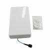
Panel and Microstrip Patch Antenna
Low-profile, rugged planar antenna designs delivering directional sector coverage. Suitable for integration into building walls, transportation equipment, cellular base stations, and space-constrained enclosures.
Broadband and Ultra-Wideband (UWB) Antenna
Designed to maintain acceptable VSWR and radiation efficiency across multi-gigahertz spans, eliminating the need to deploy multiple discrete antennas in multi-carrier or laboratory environments.
Horn Antenna (Standard Gain, Conical, and Dual-Ridge)
Low-loss aperture antennas engineered for microwave and millimeter-wave frequencies. Featuring clean, predictable radiation patterns, stable phase centers, and high power handling for calibration, laboratory measurement, and radar feeds.
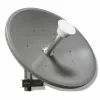
Parabolic Reflector Antenna
Combine precision parabolic surfaces with specialized feeds to deliver exceptionally high directivity, focused pencil beams, and maximum EIRP for satellite earth stations, long-haul backhaul, and tracking systems.
Helical RF Antenna
Deliver axial-mode circular polarization (RHCP/LHCP) to penetrate atmospheric disturbances and eliminate polarization mismatch loss in satellite communications, space tracking, and UAV control links.
RF Array Antenna (Phased Array)
Multi-element architectures capable of dynamic beam steering, spatial filtering, and adaptive nulling without physical movement, supporting modern 5G, SATCOM-on-the-move, and tactical radar applications.
RF Antenna Selection Guide: Key Electrical and Mechanical Parameters
Selecting an RF antenna requires evaluating electrical performance alongside mechanical and environmental constraints. Consider the following parameters when comparing products.
RF Antenna Frequency and Bandwidth
Verify operational range across the entire frequency envelope. Evaluate bandwidth criteria based on return loss limits (e.g., Return Loss ≥ 10 dB or VSWR ≤ 2.0:1) across band edges rather than relying solely on nominal center frequency performance.
Directivity, Gain (dBi/dBd), and Beamwidth
Analyze peak gain alongside half-power beamwidths (HPBW) in both the elevation (E-plane) and azimuth (H-plane). Ensure side lobe levels (SLL) and front-to-back ratios prevent self-interference and satisfy link budget requirements.
RF Antenna Impedance, VSWR, and Input Power Handling
Standard designs are matched to 50 ohms nominal impedance. Confirm peak and continuous wave (CW) power limits to avoid dielectric breakdown or thermal failure in high-power transmitters.
RF Antenna Polarization Purity
Match polarization states precisely (Linear Vertical/Horizontal, Dual-Polarized, or Circular RHCP/LHCP). Verify cross-polarization discrimination (XPD) or axial ratio (for circular polarization) to minimize transmission degradation.
Passive Intermodulation (PIM) Performance
For carrier-grade infrastructure and multi-carrier transmitters, specify dynamic PIM ratings (e.g., ≤ -153 dBc @ 2x20W) to prevent intermodulation distortion from masking weak uplink signals.
RF Antenna Connector, Mechanical, and Environmental Ruggedization
Select RF interfaces (SMA, Type N, 2.92mm, 7/16 DIN, or 4.3-10) appropriate for frequency and power requirements. Assess ingress protection (IP67/IP68), wind load resistance, radome UV stabilization, and operating temperature profiles matching field deployment environments.
Quality Assurance and RF Testing
As an ISO 9001 certified RF antenna manufacturer, iPrece operates under strict quality management systems to guarantee consistency and reliability across all production batches.
Beyond our standard rigorous inspections, we can perform any specific electrical, mechanical, or environmental test requested by the customer. From VNA impedance measurements and PIM testing to full anechoic chamber radiation pattern verification, we ensure your antenna meets the exact requirements of your deployment environment.
Streamlined Procurement: From RFQ to Global Delivery
Navigate our streamlined six-step procurement workflow, from your initial BOM submission to secure global fulfillment.
1- Requirement: Builder Configuration or BOM Submission
2- Engineering Review: Technical Specification and Configuration Verification
3- Proforma Invoice: Formal Pricing and Lead Time Issued
4- Payment: Order Confirmation and Payment Processing
5- Production: Manufacturing to Approved Specifications
6- Global Delivery: Inspection, Secure Packaging, and Shipment
RF Antenna Price
The exact RF antenna price depends on the operating frequency band, specific architectural design (such as horn, array, or omnidirectional), environmental ruggedization, order quantity, and whether the product is a standard off-the-shelf unit or a custom-engineered solution. Contact iPrece for current pricing, lead times, availability, volume discounts, and custom RF antenna quotations tailored to your project.