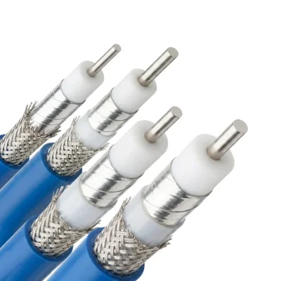


ARX Series Cable Construction and Performance
The electrical and mechanical performance of the ARX Series is determined by its conductor, dielectric, shielding, and jacket construction. Each cable uses a silver-plated copper center conductor and a low-density PTFE dielectric. The shielding structure consists of a helical silver-plated copper tape inner shield and a silver-plated copper outer braid. ARX-260, ARX-380, and ARX-520 also include an LD PTFE inner tape layer. All models use an FEP jacket.
This construction provides a nominal 50 Ω impedance, 77% velocity of propagation, capacitance of 86.8 pF/m, and shielding effectiveness greater than 90 dB. The detailed model-specific values are provided below.
ARX Coaxial Cable Material Specifications
Component and Material | ARX-150 | ARX-260 | ARX-380 | ARX-520 |
|---|---|---|---|---|
Center Conductor — Silver-Plated Copper | 0.31 mm | 0.51 mm | 0.92 mm | 1.30 mm |
Dielectric — Microporous PTFE | 0.92 mm | 1.53 mm | 2.70 mm | 3.78 mm |
Inner Shield — Helical Silver-Plated Copper Tape | 1.02 mm | 1.65 mm | 2.85 mm | 4.00 mm |
Inner Tape — LD PTFE | — | 1.95 mm | 3.15 mm | 4.25 mm |
Outer Braid — Silver-Plated Copper Braid | 1.28 mm | 2.20 mm | 3.55 mm | 4.60 mm |
Jacket — FEP | 1.50 mm | 2.60 mm | 3.85 mm | 5.20 mm |
ARX Coaxial Cable Electrical Specifications
Parameter | ARX-150 | ARX-260 | ARX-380 | ARX-520 |
|---|---|---|---|---|
Impedance | 50 Ω | 50 Ω | 50 Ω | 50 Ω |
Cut-off Frequency | 90 GHz | 46 GHz | 29 GHz | 18 GHz |
Velocity of Propagation (Vp) | 77% | 77% | 77% | 77% |
Shield Effectiveness | >90 dB | >90 dB | >90 dB | >90 dB |
Permittivity | 1.69 | 1.69 | 1.69 | 1.69 |
Delay | 4.32 nS/m | 4.32 nS/m | 4.32 nS/m | 4.32 nS/m |
Capacitance | 86.8 pF/m | 86.8 pF/m | 86.8 pF/m | 86.8 pF/m |
Voltage Withstand (DC) | 200 V | 500 V | 1000 V | 1500 V |
Peak Power | 1.2 kW | 2.5 kW | 5.6 kW | 10 kW |
ARX Series Mechanical and Environmental Specifications
Parameter | ARX-150 | ARX-260 | ARX-380 | ARX-520 |
|---|---|---|---|---|
Bend Radius — Installation | 7 mm | 12 mm | 18 mm | 25 mm |
Bend Radius — Repeated | 15 mm | 24 mm | 36 mm | 50 mm |
Weight | 13 g/m | 18 g/m | 36 g/m | 65 g/m |
Operating Temperature | -55°C to +165°C | -55°C to +165°C | -55°C to +165°C | -55°C to +165°C |
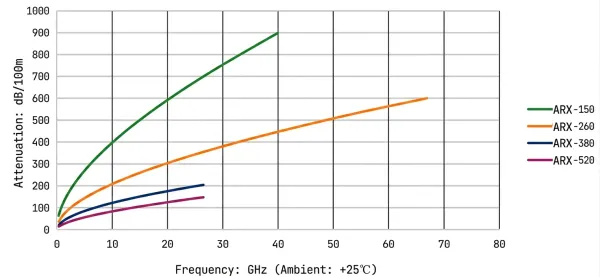
ARX Series Attenuation vs. Frequency
The following manufacturer-provided values are expressed in dB per 100 m. A dash indicates that the reference does not provide a value at that frequency for the corresponding model.
Frequency (MHz) | ARX-150 | ARX-260 | ARX-380 | ARX-520 |
|---|---|---|---|---|
300 | 61.30 | 34.20 | 20.30 | 12.60 |
1,000 | 114.30 | 63.10 | 37.30 | 23.60 |
3,000 | 204.60 | 111.20 | 65.30 | 42.50 |
6,000 | 298.50 | 159.70 | 93.50 | 62.30 |
8,000 | 350.30 | 186.00 | 108.50 | 73.30 |
12,000 | 440.50 | 231.00 | 134.20 | 92.40 |
18,000 | 556.80 | 287.70 | 166.30 | 117.20 |
26,500 | 700.00 | 355.90 | 204.50 | 148.00 |
40,000 | 898.90 | 448.00 | 256.00 | — |
50,000 | — | 508.50 | — | — |
60,000 | — | 564.70 | — | — |
67,000 | — | 601.90 | — | — |
ARX Series Attenuation Models
In the following equations, f is frequency in MHz and A(f) is nominal attenuation in dB/100 m. Each equation should be used only within the published attenuation reference range for its model.
ARX-150
ARX-260
ARX-380
ARX-520
These empirical models should not be extrapolated beyond the published attenuation data or used as a substitute for measured values at unlisted frequencies.
ARX Series Power Handling vs. Frequency
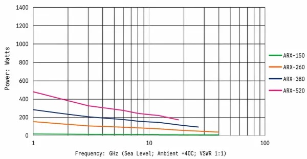
The following manufacturer-provided values represent maximum power-handling references at the listed frequencies. Actual permissible power depends on operating temperature, duty cycle, cooling conditions, VSWR, and the final system configuration.
Frequency (MHz) | ARX-150 (W) | ARX-260 (W) | ARX-380 (W) | ARX-520 (W) |
|---|---|---|---|---|
300 | 50 | 500 | 950 | 1,608 |
1,000 | 27 | 271 | 517 | 860 |
3,000 | 15 | 154 | 285 | 479 |
6,000 | 10 | 107 | 206 | 327 |
8,000 | 9 | 92 | 177 | 278 |
10,000 | 8 | 86 | 158 | 245 |
12,000 | 7 | 74 | 143 | 221 |
18,000 | 6 | 59 | 116 | 174 |
26,500 | 4 | 48 | 94 | 138 |
40,000 | 3 | 38 | 75 | — |
50,000 | — | 34 | — | — |
60,000 | — | 30 | — | — |
67,000 | — | 28 | — | — |
Peak Power in the Electrical Specifications table is a separate parameter and should not be interpreted as the continuous maximum power-handling value at every frequency.
ARX Series Performance Curves
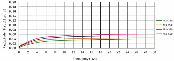
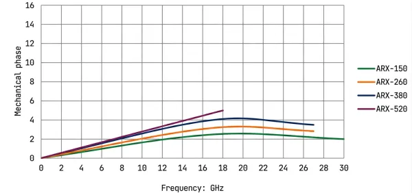
The following manufacturer-provided curves complement the numerical specifications and show attenuation, power handling, amplitude stability, mechanical phase stability, and phase change rate across the corresponding frequency, bending, or temperature conditions.
Attenuation vs. Frequency
Power Handling vs. Frequency
Amplitude Stability During Repeated Bending
Phase Stability During Repeated Bending
Phase Change Rate vs. Temperature
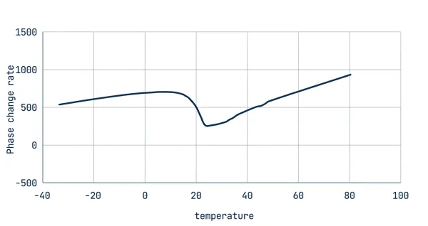
Mechanical phase and amplitude stability are evaluated by monitoring the cable response during one complete rotation along the specified repeated bend radius. The temperature-related phase curve represents the corresponding static thermal test condition. Numerical PPM claims are not repeated in this category description.