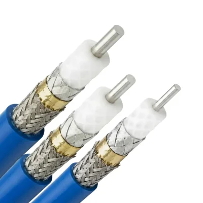


The HPX Series is a family of 50 Ω high-performance flexible coaxial cables designed for demanding RF and microwave interconnect applications. The series combines low-loss signal transmission, high shielding effectiveness, mechanical stability during bending, and high power-handling capability across models with cut-off frequencies from 23.09 to 35.4 GHz.
HPX Series Features and Applications
HPX cables are intended for high-frequency systems where attenuation, shielding, mechanical stability, power handling, and environmental capability must be considered together.
50 Ω characteristic impedance
Cut-off frequencies from 23.09 to 35.4 GHz
Shielding effectiveness greater than 100 dB
76% velocity of propagation
76% microporous PTFE dielectric
Triple-layer composite shielding
Operating temperature range from −55°C to +165°C
Maximum stable environmental temperature of +200°C when compatible connectors and assembly materials are used
Mechanical phase and amplitude stability during repeated bending
Typical applications include military radar systems, aerospace communications, high-performance RF systems, microwave test and measurement equipment, and other demanding RF interconnect applications.
HPX Series Mechanical Dimensions
Dimension | HPX-460 | HPX-520 | HPX-630 |
|---|---|---|---|
Center Conductor Diameter | 1.02 mm | 1.30 mm | 1.57 mm |
Dielectric Diameter | 2.97 mm | 3.75 mm | 4.60 mm |
Inner Shield Diameter | 3.15 mm | 3.95 mm | 4.80 mm |
Interlayer Diameter | 3.30 mm | 4.10 mm | 5.00 mm |
Jacket Diameter | 3.70 mm | 4.50 mm | 5.40 mm |
Outer Diameter | 4.50 mm | 5.20 mm | 6.00 mm |
HPX Series Electrical Data
Parameter | HPX-460 | HPX-520 | HPX-630 |
|---|---|---|---|
Impedance | 50 Ω | 50 Ω | 50 Ω |
Velocity of Propagation | 76% | 76% | 76% |
Shielding Effectiveness | >100 dB | >100 dB | >100 dB |
Dielectric Constant | 1.73 | 1.73 | 1.73 |
Time Delay | 4.39 ns/m | 4.39 ns/m | 4.39 ns/m |
Capacitance | 87.7 pF/m | 87.7 pF/m | 87.7 pF/m |
Voltage Withstand | 1000 VDC | 1500 VDC | 2000 VDC |
Peak Power | 2.5 kW | 5.6 kW | 10 kW |
Cut-off Frequency | 35.4 GHz | 27.84 GHz | 23.09 GHz |
HPX Series Mechanical Data
Parameter | HPX-460 | HPX-520 | HPX-630 |
|---|---|---|---|
Minimum Bend Radius: Installation | 19.1 mm | 25.4 mm | 31.8 mm |
Minimum Bend Radius: Repeated | 46 mm | 52 mm | 63 mm |
Weight | 50 g/m | 60 g/m | 90 g/m |
Operating Temperature Range | −55°C to +165°C | −55°C to +165°C | −55°C to +165°C |
Maximum Stable Environmental Temperature | +200°C | +200°C | +200°C |
The +200°C value refers to the maximum stable environmental temperature stated for the cable construction. The applicable temperature limit of a completed cable assembly also depends on the selected connectors, termination materials, and assembly design.
HPX Series Material Construction
Cable Layer | HPX-460 | HPX-520 | HPX-630 | Material Composition |
|---|---|---|---|---|
Center Conductor | 1.02 mm | 1.30 mm | 1.57 mm | Silver-Plated Copper |
Dielectric | 2.97 mm | 3.75 mm | 4.60 mm | Microporous PTFE, 76% |
Inner Shield | 3.15 mm | 3.95 mm | 4.80 mm | SPC Flat Silver Tape |
Interlayer | 3.30 mm | 4.10 mm | 5.00 mm | Metalized Composite Tape or Aluminum Foil |
Jacket | 3.70 mm | 4.50 mm | 5.40 mm | FEP |
Outer Sheath | 4.50 mm | 5.20 mm | 6.00 mm | Polyperfluoroethylene Propylene |
HPX Series Attenuation vs. Frequency
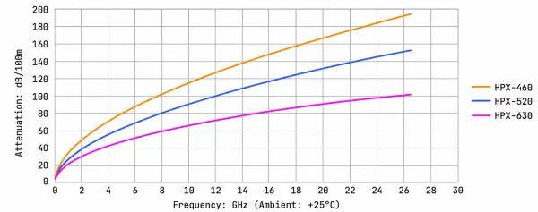
Attenuation varies with operating frequency and cable length. The following manufacturer-provided values are expressed in dB per 100 m. For a complete link-loss estimate, connector, termination, and assembly losses should be evaluated separately.
Frequency | HPX-460 | HPX-520 | HPX-630 |
|---|---|---|---|
50 MHz | 7.80 dB/100 m | 6.08 dB/100 m | 4.86 dB/100 m |
300 MHz | 19.22 dB/100 m | 15.01 dB/100 m | 12.00 dB/100 m |
500 MHz | 24.88 dB/100 m | 19.44 dB/100 m | 15.56 dB/100 m |
1 GHz | 35.36 dB/100 m | 27.67 dB/100 m | 22.18 dB/100 m |
2 GHz | 50.35 dB/100 m | 39.47 dB/100 m | 31.71 dB/100 m |
4 GHz | 71.90 dB/100 m | 56.52 dB/100 m | 45.54 dB/100 m |
6 GHz | 88.71 dB/100 m | 69.87 dB/100 m | 56.43 dB/100 m |
10 GHz | 115.85 dB/100 m | 91.53 dB/100 m | 74.18 dB/100 m |
12 GHz | 127.53 dB/100 m | 100.88 dB/100 m | 81.88 dB/100 m |
16 GHz | 148.52 dB/100 m | 117.76 dB/100 m | 95.81 dB/100 m |
18 GHz | 158.14 dB/100 m | 125.51 dB/100 m | 102.23 dB/100 m |
26.5 GHz | 194.63 dB/100 m | 155.04 dB/100 m | Not specified |
HPX Series Power Handling vs. Frequency
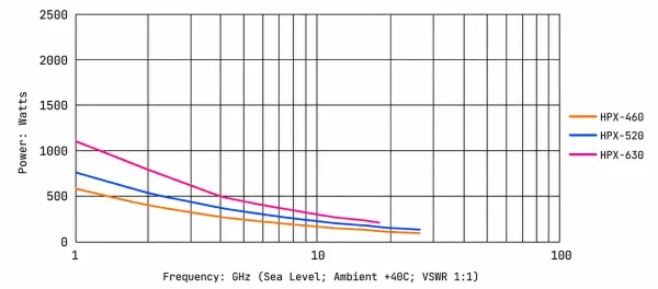
Power handling is frequency-dependent. As frequency increases, the maximum applicable power generally decreases because conductor loss, dielectric loss, and thermal loading become more significant.
Frequency | HPX-460 | HPX-520 | HPX-630 |
|---|---|---|---|
50 MHz | 2618 W | 3452 W | 4690 W |
300 MHz | 1063 W | 1399 W | 1898 W |
500 MHz | 825 W | 1085 W | 1502 W |
1 GHz | 580 W | 760 W | 1100 W |
2 GHz | 410 W | 535 W | 793 W |
4 GHz | 285 W | 375 W | 505 W |
6 GHz | 233 W | 306 W | 408 W |
10 GHz | 180 W | 233 W | 312 W |
12 GHz | 160 W | 211 W | 281 W |
16 GHz | 148 W | 188 W | 251 W |
18 GHz | 130 W | 168 W | 228 W |
26.5 GHz | 107 W | 145 W | Not specified |
These maximum power values should be interpreted together with operating temperature, duty cycle, cooling conditions, VSWR, connector capability, and assembly configuration. They should not be confused with the model-specific Peak Power values listed in the Electrical Data table.
HPX Series Performance Curves
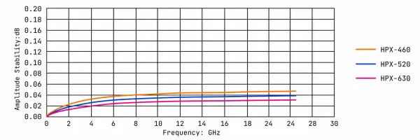
The following manufacturer-provided curves complement the numerical tables and illustrate attenuation, power handling, amplitude stability, and mechanical phase stability across the corresponding operating and test conditions.
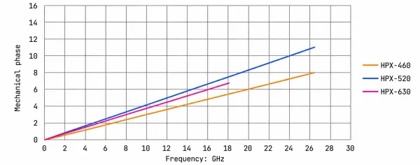
Mechanical Phase and Amplitude Stability Test Method
Mechanical phase and amplitude stability are evaluated by applying one complete rotation along the specified repeated bend radius while monitoring the cable response. This test identifies performance variation caused by mechanical flexure.
The manufacturer also provides a phase-change-versus-temperature reference curve. Because the numerical PPM result has not been independently laboratory-validated for publication, no numerical PPM value is stated here.
HPX Series Conductor and Shielding Structure
The HPX Series uses a silver-plated copper center conductor and a 76% microporous PTFE dielectric. The outer shielding structure combines SPC flat silver tape, a high-temperature aluminum-foil or metalized-composite interlayer, and a silver-plated copper wire braid. This three-layer construction is designed to support shielding effectiveness, mechanical stability, resistance to signal variation during bending, and long service life.
Connector configurations can be selected for the intended frequency, cable model, geometry, and application. The manufacturer reference identifies SMA, N, TNC, 3.5 mm, 2.92 mm, and other connector options. The detailed reference selection table below lists the connector combinations documented for the HPX Series.
HPX Series Connector Selection Reference
Connector Type | Connector Position | Connector Code | Working Frequency | HPX-460 | HPX-520 | HPX-630 | Typical Standing Wave |
|---|---|---|---|---|---|---|---|
3.5 mm | Male | 35M | 26.5 GHz | TS-35MS480-01 | Not specified | Not specified | 1.25 |
3.5 mm | Female | 35F | 26.5 GHz | TS-35FS480-01 | Not specified | Not specified | 1.25 |
SMA | Male | SM | 26.5 GHz | TS-SM460-01 | TS-SM520-02 | Not specified | 1.25 |
SMA | Male | SM | 18 GHz | Not specified | Not specified | TS-SM630-01 | 1.20 |
SMA | Male-RA | SM(RA) | 18 GHz | TS-SM460-RA-01 | TS-SM520-RA-01 | Not specified | 1.25 |
SMA | Female | SF | 18 GHz | TS-SF460-01 | TS-SF520-01 | Not specified | 1.20 |
N | Male | NM | 18 GHz | TS-NM460-01 | TS-NM520-01 | TS-NM630-01 | 1.20 |
N | Male-RA | NM(RA) | 18 GHz | TS-NM460-RA-01 | TS-NM520-RA-01 | Not specified | 1.25 |
N | Female | NF | 18 GHz | TS-NF460-01 | TS-NF520-01 | Not specified | 1.25 |
TNC | Male | TM | 18 GHz | TS-TM460-01 | TS-TM520-01 | TS-TM630-01 | 1.25 |
TNC | Female | TF | 11 GHz | TS-TF460-01 | Not specified | Not specified | 1.25 |
The connector codes and typical standing-wave values in this table are reference selections from the manufacturer data. Final connector compatibility should be confirmed against the required frequency, cable model, bend configuration, power level, and completed assembly design.