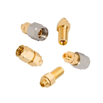
2.92 mm RF Connector Design and Interface
The 2.92 mm designation refers to the inner diameter of the connector’s outer conductor. Its air-dielectric interface, shortened male pin, and reinforced outer conductor support repeatable mating with reduced contact wear. The interface is also mechanically compatible with SMA and 3.5 mm connectors, although the complete signal path remains limited by the lowest-rated component.
Available 2.92 mm K Connector Types
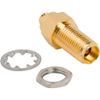
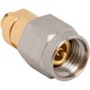
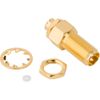
iPrece supplies cable-mount plugs and bulkhead jacks for 0.085/0.086-inch and 0.141-inch cable families, along with solderless PCB jacks for microstrip and stripline designs.
The available range falls into two installation categories:
Cable-mount 2.92 connectors
Solderless PCB-mount 2.92 connector
Products within these categories differ by gender, mounting arrangement, cable compatibility, and PCB transmission structure.
2.92 mm Connector Cable Mount
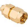
Cable-mount options include straight solder plugs and straight rear-mount bulkhead jacks. They are available for 0.085/0.086-inch cable families such as RG-405 and for 0.141-inch cable families such as RG-402, including semi-rigid and conformable variants. Plugs terminate the end of a cable, while bulkhead jacks create a fixed interface through an equipment panel or enclosure.
Solderless PCB-Mount 2.92 K Connector
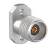
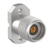
PCB-mount options are straight solderless surface-mount jacks designed for either microstrip or stripline transmission structures. Their solderless attachment simplifies installation and removal while avoiding the variability introduced by a solder joint at the connector-to-board transition.
2.92 mm Connector Frequency Range and Specifications
The 2.92 mm connector frequency range extends from DC to 40 GHz, supporting microwave and millimeter-wave signal paths that exceed the typical operating range of standard SMA interfaces. All available models use a 50 Ω threaded interface, with specifications varying according to cable or PCB configuration.
The complete signal path must also be evaluated at the required operating frequency. Cable performance, PCB launch design, mating-interface condition, and installation quality can affect VSWR and insertion loss, even when the selected 2.92 mm K connector is rated to 40 GHz.
K Connector Selection Requirements
Most issues arise at the cable, PCB, or mating interface rather than the connector itself. Use the following checks to avoid common errors when selecting the right 2.92 mm connector:
Verify full transition data (VSWR/return loss) where available. Poor cable choice or PCB launch can degrade the expected 40 GHz system performance.
Match the connector to the specific PCB stack-up. Microstrip and stripline versions require different launch designs, so follow layout guidelines strictly.
Match the correct cable family. 0.085/0.086 in and 0.141 in connectors are not interchangeable due to dimensional and impedance differences.
Verify bulkhead access. Rear-mount jacks require internal installation; confirm panel thickness, hole size, and tool clearance early.
Handle SMA mating carefully. Inspect pins, keep the body fixed, rotate only the nut, and use a torque wrench to spec.
Plan for wear in test setups. Even with ~500-cycle ratings, contamination and overuse reduce life—use port savers for frequent connections.
Check temperature ratings per type. Cable-mount up to +165°C; solderless PCB versions typically limited to +85°C.
Include cable/PCB details, mounting, frequency, environment, and test requirements in the RFQ for proper review.
Custom 2.92 mm RF Connector and OEM Support
iPrece can review custom cable-mount, bulkhead, and solderless PCB 2.92 mm connector requirements. Options may include alternative cable terminations, panel geometry, body finish, and PCB launches for specific microstrip or stripline stack-ups.
For technical review, provide:
Target frequency and VSWR or return-loss requirement
Cable family or PCB stack-up
Plug or jack gender and mounting arrangement
Temperature and mating-cycle requirements
Prototype and production quantities
Required drawings, test data, and compliance documents
OEM support can include part-number cross-referencing, prototype development, mechanical drawings, production supply, and 100% VNA testing by iPrece.