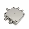
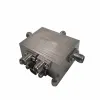
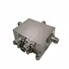
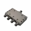
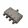
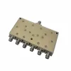
RF Switch Specifications
Compare RF switches by frequency coverage, insertion loss, isolation, switching speed, and power handling. The ranges below summarize representative commercial designs. Exact specifications depend on the selected model, frequency, signal path, and operating conditions.
Configurations and Frequency Coverage
Specification | Common Options / Reference Range |
|---|---|
Switch technology | Electromechanical, PIN diode, FET / SOI |
Configuration | SPST, SPDT, DPDT / transfer, SP4T, SP6T, SP8T, SP12T |
Nominal impedance | 50 Ω; selected 75 Ω designs |
Lower frequency limit | DC, kHz, or MHz, depending on design |
Upper frequency options | 6, 18, 26.5, 40, 50, or 67 GHz |
Off-state termination | Reflective or absorptive |
Insertion Loss, Isolation, and RF Matching
Specification | Electromechanical | Solid-State |
|---|---|---|
Insertion loss | Approx. 0.1–1.2 dB | Approx. 0.3–6 dB |
Isolation | Approx. 60–100+ dB | Approx. 20–90 dB |
Selected-path VSWR | Approx. 1.1:1–1.9:1 | Approx. 1.2:1–2.0:1 |
Switching Speed and Operating Life
Specification | Approximate Range / Options |
|---|---|
Electromechanical switching time | 15–25 ms |
PIN diode switching time | 50 ns–10 µs |
FET / SOI switching time | 8 ns–10 µs |
RF settling time, selected solid-state designs | 2–10 µs |
Electromechanical operating life | 1–10 million cycles |
Precision electromechanical repeatability | 0.03–0.1 dB |
RF Power Handling and Linearity
Specification | Approximate Reference Range |
|---|---|
General-purpose solid-state through power, CW | 0.5–4 W (+27 to +36 dBm) |
High-power PIN diode through power, CW | 10–100 W (+40 to +50 dBm) |
Electromechanical through power, CW | 1–20 W |
Internal termination power | 0.1–2 W |
Input P1dB, selected solid-state designs | +27 to +40 dBm |
IIP3, selected solid-state designs | +48 to +66 dBm |
Power Supply and Control
Specification | Common Options / Reference Range |
|---|---|
FET / SOI supply voltage | Approx. 2.3–5.5 V DC |
PIN diode module supply | Commonly +5, +12, or +15 V DC |
Electromechanical coil voltage | 5, 12, 15, or 24 V DC |
Negative supply | Required by some solid-state designs |
Direct control | TTL / CMOS logic; coil drive |
Serial control, selected modules | SPI, I²C |
Instrument control, selected modules | USB, Ethernet |
Electromechanical actuation | Latching or failsafe |
Packaging, Interfaces, and Temperature
Specification | Common Options / Reference Range |
|---|---|
Package format | Connectorized module, surface-mount IC, bare die |
RF connectors | SMA, N-Type, 2.92 mm, 2.4 mm, 1.85 mm |
Representative IC footprint | Approx. 3 × 3 to 5 × 5 mm |
Common electronic operating range | −40 °C to +85 °C |
Extended-temperature options | −55 °C to +125 °C |
How to Choose the Right RF Switch
Start by identifying which signal paths need to be connected, disconnected, or selected. Switching between two RF paths has different requirements from routing signals among several channels or controlling a high-power transmission path.
Before selecting an RF switch, evaluate:
Port configuration: Determine whether the application requires SPDT, DPDT, SP4T, SP6T, or another switching arrangement.
Frequency range: Confirm that the entire operating band is covered.
Insertion loss: Evaluate the power lost through the selected path.
Isolation: Determine how effectively unwanted signals are suppressed between ports.
Switching time: Match switching speed and signal settling requirements to the system timing.
Power handling: Check the permitted RF power under the intended frequency and operating conditions.
Impedance and connectors: Confirm compatibility with the connected equipment.
Control requirements: Verify supply voltage, control logic, current consumption, and driver requirements.
The best RF switch is the one that satisfies the complete electrical, timing, and integration requirements—not simply the one with the highest power rating or fastest switching speed.
RF Switch Applications
RF switches enable fast, reliable routing of high-frequency signals between antennas, filters, instruments, and redundant communication paths.
Automated Test and Measurement
RF switches connect shared instruments to multiple devices or test ports in automated test systems. They sequence measurements electronically, reducing manual reconnections during production testing, component characterization, and laboratory measurements.
For repeated measurements, consider switches with documented insertion-loss repeatability and settling times that fit the test sequence. For high-cycle testing with electromechanical switches, also evaluate rated switching life.
Transmit/Receive Switching
RF switches alternate a shared antenna between transmitter and receiver paths in time-division radios and pulsed radar. During transmission, they isolate the receive path from the active transmitter.
Consider switches with power ratings that cover the transmitter’s CW or pulse conditions and TX-to-RX isolation that meets the receiver’s leakage budget. Check the hot-switching rating when RF power remains present during state changes.
Antenna Routing and Diversity
In antenna diversity systems, RF switches connect a receiver to different antennas as reception conditions change. They also route radios between antennas serving different frequency bands or coverage areas.
Consider a configuration with enough ports for the antenna branches and insertion loss compatible with the receiver’s sensitivity budget. For rapid antenna selection, check that switching and settling fit the available selection interval.
Filter Bank Switching
RF switches route signals through selected filters in multiband radios and receiver front ends. Switching between filter paths changes the active passband or bandwidth as operating channels and modes change.
Consider a port configuration that accommodates the filter paths and isolation that keeps unselected-path leakage within the required rejection budget. Check that unused-port termination behavior is compatible with the filters’ out-of-band impedance.
Redundancy in Communication Links
RF switches reroute signals from a primary RF path to a standby path in microwave communication systems. This allows backup equipment to take over during faults, maintenance, or planned changeovers.
Consider a latching configuration when the last selected path must remain selected after control power is lost. Where the system requires a return to a defined path, consider a failsafe configuration with that specified default state. Match changeover time to the permitted interruption.
RF Signal Monitoring
RF switches connect multiple antenna feeds or sampled RF paths to a shared monitoring receiver or spectrum analyzer. Sequential routing lets one instrument inspect different channels, transmitters, or system locations.
For sequential scans, consider enough input ports for the feeds and settling times that leave sufficient time for each measurement. Where signal levels differ substantially, prioritize isolation that limits leakage from stronger unselected signals.
Quality & Standards
iPrece combines controlled manufacturing, RF testing, and traceability to support dependable component sourcing—from initial design review through OEM production.
ISO 9001: 2015 quality management: Certified quality processes support consistent manufacturing, inspection, and control of product requirements.
RF performance verification: Calibrated VNA testing checks insertion loss and VSWR against applicable product specifications before shipment.
Mechanical and electrical validation: Components and RF modules undergo pre-shipment checks for construction quality and datasheet compliance.
RoHS and REACH compliance: iPrece lists both within its compliance framework; applicable declarations should be confirmed for the selected part.
Environmental validation capabilities: Thermal cycling, humidity exposure, and shock validation support projects with demanding operating requirements. Qualification scope remains specific to the selected model.
Include any required compliance declarations, test reports, or environmental qualifications in your RFQ so they can be confirmed before ordering.
Request an RF Switch Quote
Contact our sales and RF engineering teams for pricing, availability, or help reviewing your requirements.
Share the part number or specifications. Include the required quantity and target delivery date. If you have not selected a part, provide the operating frequency, impedance, port configuration, RF power levels, and control requirements.
Include supporting information. Upload drawings, specifications, or a BOM through the inquiry form. Identify any mechanical constraints, custom requirements, testing, or documentation needed for your project.
Confirm the technical and commercial details. Discuss component specifications and integration requirements with our RF engineers. Confirm the selected configuration, pricing, inventory status, and production lead time with sales before ordering.