SMA to SMA Cable
For RF modules, test equipment, antennas, and general microwave interconnects.
Configure →Balance insertion loss, bend radius and connector clearance in RF and microwave interconnects. Specify standard or custom SMA cable assemblies using flexible, low-loss, hand-formable or semi-rigid coax, with phase-matched SMA cables for multichannel systems. Options include male-to-male and male-to-female SMA-to-SMA cables and transitions to BNC, N-Type, TNC, SMB, MCX, MMCX, SMP, SMPM and U.FL, with straight or right-angle terminations and bulkhead mounting. Request a quote for custom RF cable assemblies with finished length, connector clocking and RF limits across your operating band.
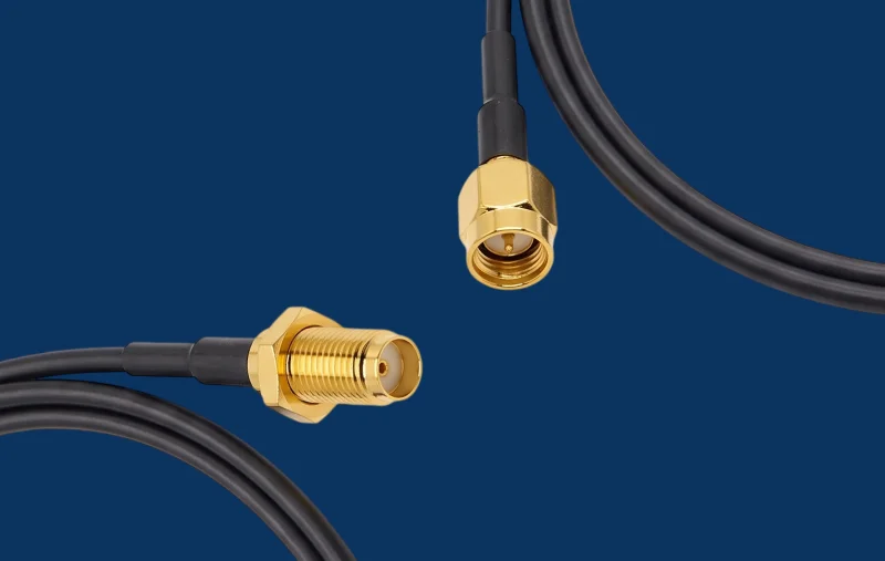
Submit your custom RF requirements for a verified technical review and formal wholesale pricing within 24 hours.
These common SMA configurations cover RF testing, communications equipment, and embedded systems. Configure your exact requirements using our custom RF cable assemblies tool.
For RF modules, test equipment, antennas, and general microwave interconnects.
Configure →Connects compact SMA ports to BNC-based test, radio, and communications equipment.
Configure →Links SMA equipment with F Type broadband or video hardware; confirm impedance compatibility.
Configure →Connects SMA equipment to ultracompact antenna and embedded RF ports.
Configure →Connects compact RF devices to rugged antenna, base-station, and outdoor interfaces.
Configure →Links threaded SMA equipment with quick-connect SMB ports in compact RF systems.
Configure →Review baseline parameters, then select a compatible cable family to configure your assembly.
| Cable | Best for | Flexibility | Loss | Impedance |
|---|---|---|---|---|
| Flexible RF coax | General RF and test connections | High | Moderate | 50 Ω |
| Low-loss flexible | Longer RF and antenna runs | Medium–high | Low | 50 Ω |
| Semi-rigid | Precision fixed routing | Low | Low | 50 Ω |
| Hand-formable | Compact controlled routing | Medium | Low | 50 Ω |
| Phase-stable microwave | Test systems and phase-critical paths | Medium | Low | 50 Ω |
Final compatibility and performance are confirmed during engineering review.
We engineer your custom SMA cable assembly to deliver predictability across standard, formed, and matched configurations for production, test, and microwave hardware.
Selected assemblies operate through 34 GHz for microwave connections beyond the standard 18 GHz range.
Selected semi-rigid builds provide up to 120 dB shielding at 18 GHz to limit leakage and interference.
Computer-controlled forming supports bend radii from 1.27 mm and tolerances as tight as ±0.76 mm (±0.030″).
Phase, delay, and amplitude matching keeps parallel RF paths aligned in radar, array, and test systems.
SMA connector cable assemblies route high-frequency signals through compact systems where secure mating and repeatable RF performance matter.
Connect VNAs, generators, analyzers, and test fixtures.
Link amplifiers, filters, mixers, switches, and transceivers.
Connect radios, antennas, base stations, and WLAN equipment.
Support radar, avionics, SATCOM, and electronic warfare systems.
An SMA cable assembly is a ready-to-use 50 Ω RF connection made from a coaxial cable with SMA connectors attached to one or both ends. Each SMA coaxial cable assembly is delivered as a complete, plug-and-play signal path.
iPrece supports 50 Ω SMA cable assemblies using flexible, low-loss, conformable, semi-rigid, and specialized coaxial cables. Available frequency coverage extends from DC to 18 GHz, depending on the cable, SMA termination design, assembly length, body style, and required VSWR.
Every SMA cable assembly is electrically tested and inspected to applicable industry and military requirements. Test reports are available for customer qualification and incoming QA.
Continuity and Hi-Pot tests verify conductor continuity, dielectric isolation, and termination integrity.
VNA test reports verify insertion loss and VSWR through the specified operating range, including configurations up to 18 GHz.
Phase matching as tight as ±2 ps is available for selected semi-rigid SMA cables used in radar and multichannel RF modules.
Selected custom SMA assemblies support frequencies up to 18 GHz. The actual limit depends on the cable type, SMA interface, assembly length, body style, bends, and required VSWR.
Both materials are available. Stainless steel provides greater mechanical durability and mating stability, while brass offers lower cost, lighter weight, and good electrical conductivity.
Yes. Mixed-interface assemblies can connect SMA to MCX, MMCX, N, TNC, QMA, 2.92 mm, 3.5 mm, and other compatible RF interfaces.
Both options are available. Pre-formed assemblies can be manufactured to customer-defined bends, reference-plane dimensions, interface clocking, and mounting locations.
Yes. We provide phase, delay, and amplitude-matched sets, with tolerances as tight as ±2 ps for selected configurations and frequencies.
Yes. iPrece can manufacture or cross-reference an assembly from a drawing, CAD model, BOM, reference sample, or existing manufacturer part number.
Select your specifications online or upload complete drawings for engineering review.