What Are Blind-Mate RF Connectors? Types, Applications, and Selection Criteria


Blind-mate RF connectors are designed to connect without the operator seeing or aligning each connector by hand or a wrench. The connectors slide or snap into place, bringing the matching contacts together to carry the RF signal. The equipment guides them into position as a board or module is inserted, and sloped lead-in surfaces on the connectors help correct small alignment errors.
Blind-mate connectors are used where connections are hidden, difficult to reach, or need to be made at the same time. Common examples include removable RF modules, rack-mounted equipment, board-to-board connections, radar systems, and automated test fixtures. In these arrangements, inserting a board or module can complete several RF connections in one movement.
Types of Blind-Mate RF Connectors
Blind-mate RF interconnects differ in how the connectors join and how they are mounted. Direct-mating and bullet-based designs describe the connection. Fixed and floating designs describe the mounting. These features can be combined: a bullet, for example, can join two fixed connectors.
Floating Blind-Mate RF Connectors
Floating-mount connectors can move a small distance within their mounts. As the parts are pushed together, guides and sloped lead-in surfaces move the floating connector into line with its mate. The board or panel itself can stay in place.
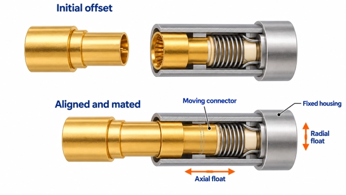
The movement may take one or more forms:
Axial float: The connector moves forward or backward along the direction of insertion.
Radial float: The connector moves sideways to meet an off-center mating connector.
Angular movement: The connector tilts slightly, where the design allows it.
The movement allowed during insertion may differ from the movement allowed after connection. The capture or connecting range describes how far out of line the parts can start and still connect. The working range describes the movement allowed once they are connected. Both depend on the particular connector and mounting arrangement.
Several blind-mate connections can also be grouped in multi-port RF interconnects. A shared housing holds the RF interfaces so they connect together when a board or module is inserted. The housing may contain fixed or floating elements, depending on the design.
Fixed Blind-Mate RF Connectors
Fixed-mount connectors are held in a set position on a PCB, panel, or housing. Their bodies do not move to follow the mating connector, so the equipment’s guides must bring the two sides close enough to connect.
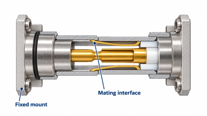
A fixed mount can still be part of a connection that allows some movement. Two fixed SMP receptacles, for example, can handle small differences in position through the bullet between them. The receptacles remain fixed while the bullet moves at its ends.
Direct-Mating Blind-Mate Interconnects
A direct-mating connection uses two parts: a plug and a matching receptacle. They connect directly, without a separate adapter between them. BMA connectors commonly use this arrangement.
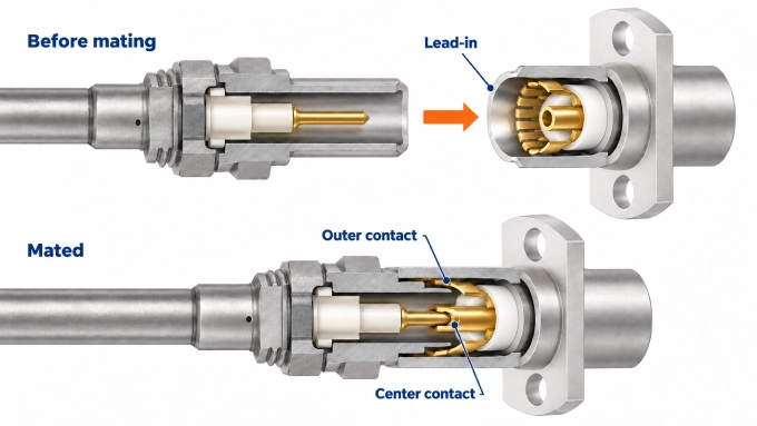
Chassis rails or guide pins bring the parts close to alignment. Sloped surfaces at the connector opening then help the plug enter the receptacle, bringing the matching RF contacts together.
The RF connection and the module’s fastening system serve different purposes. A separate latch or fastener may hold the module in place and keep the connectors at the correct mating depth.
Bullet-Based Blind-Mate Interconnects
A bullet-based connection uses a short coaxial adapter, called a bullet, between two receptacles. SMP and SMPM board-to-board connections often use this arrangement, with one receptacle on each board.
The bullet can tilt at its ends to bridge a small sideways offset between the receptacles. It can also slide slightly in or out of a smooth-bore receptacle as the gap between the boards changes. The bullet itself stays rigid; the movement occurs at its connections.
The receptacles determine how firmly the bullet is held:
A smooth bore lets the bullet slide without a retaining step.
A limited detent, where available, grips the bullet with moderate force.
A full detent holds it more firmly and requires more force to pull apart.
A common arrangement uses a detent on one board and a smooth bore on the other. When the boards separate, the bullet stays attached to the side with the detent. Some adapters also include springs to help keep the contacts engaged as the spacing changes.
Which RF Connector Families Support Blind Mating?
BMA, SMP, SMPM, SMPS, and P-SMP all support blind mating. They differ mainly in size, frequency range, power handling, and the ways they attach to a board, panel, or cable.
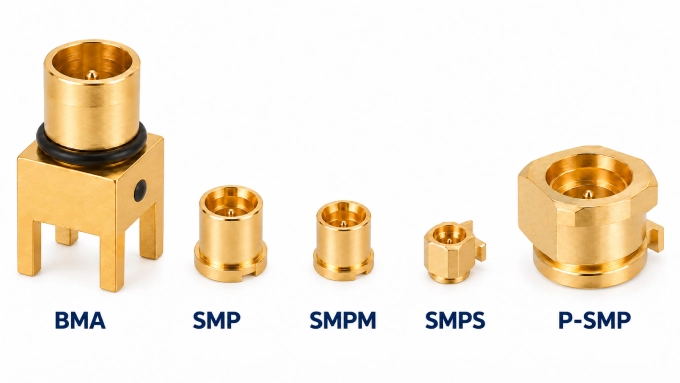
BMA Connectors
BMA connectors use a slide-on interface for direct blind mating. They are available as cable connectors, PCB receptacles, and panel-mounted parts, with both fixed and floating mounting options. Cable versions support flexible and semi-rigid coaxial cables.
Most manufacturers specify their BMA range for operation from DC to 22 GHz. Its fixed and floating versions have different alignment limits, so the mounting arrangement forms part of the connector specification.
SMP Connectors
SMP is a compact microwave connector family used for both direct cable connections and bullet-based board connections. It includes straight and right-angle cable connectors, PCB receptacles, panel-mounted connectors, and bullets in different lengths.
Smooth-bore, limited-detent, and full-detent versions offer different holding forces. This gives designers a choice between connections that separate easily and those that grip more firmly. SMP range is specified from DC to 26.5 GHz, and extended up to 40 GHz in select variations.
SMPM Connectors
SMPM has a smaller mating interface than SMP, allowing more RF connections to fit into a limited area. It comes in smooth-bore and full-detent versions for cable and board connections. PCB options include surface-mount, through-hole, and edge-launch parts.
Some manufacturers offer extended-range SMPM designs rated up to 65 GHz. In a board connection, the receptacles, bullet, and transition between the connector and PCB trace must all support the required frequency range.
SMPS Connectors
SMPS reduces the connector size further than SMPM. It is useful when many RF contacts must fit into a small housing or closely spaced set of connections. Available parts include PCB connectors, cable contacts, and adapters.
Some manufacturers list 65 GHz operation for their SMPS backplane interconnects. The small contacts need careful handling, and the board or module must keep them accurately positioned during connection and removal.
P-SMP Connectors
P-SMP is designed for compact connections that need higher RF power handling. The family includes PCB connectors, cable connectors, panel-mounted parts, and bullets for board-to-board connections. Although the name resembles SMP, P-SMP uses a different mating interface.
What Are the Advantages and Disadvantages of Blind Mating?
Blind mating makes installation and module replacement easier when RF connections are hidden or crowded together. It shifts the job of lining up the connectors from the operator to the equipment.
Advantages
Connections in hidden spaces. Operators do not need to reach or tighten each RF connector.
Several connections in one action. Inserting a board or module can join multiple RF paths at once.
Some alignment errors are allowed. Floating mounts and bullet connections can handle small differences in position between the mating parts.
Easier module replacement. A module can be removed without disconnecting each RF cable separately.
Disadvantages
More mechanical design work. Guides, stops, and mounts must position the connectors correctly and control mating depth. Extra mounts or carriers add parts and dimensions to check.
More force may be needed for insertion. Multiple connectors can increase the force needed to insert or remove a module. Uneven entry can also cause it to bind.
Movement is limited. Position errors across boards, panels, and mounts can add together and exceed the movement the connection allows.
Contact wear requires maintenance. Repeated mating can wear the contacts. They need inspection, and worn or damaged parts may need replacement.
Where Are Blind-Mate RF Connectors Used?
Blind-mate RF connectors are used inside equipment where RF ports are hidden or several connections must be made together.
Removable RF Modules
Blind-mate connectors join the RF inputs and outputs of a removable receiver, amplifier, or transceiver module to ports on a chassis or backplane. The connections are made as the module enters its slot and separate when it is withdrawn. A technician can replace the module without reaching behind it to handle individual coaxial cables.
Board-to-Board Connections
Blind-mate connectors carry RF signals between a daughterboard and a main board, or between two stacked boards. These boards may contain separate amplifier, filter, or frequency-conversion circuits. Their RF ports meet as the boards are assembled, avoiding the need to reach into the narrow gap and attach individual cables.
Radar and Phased-Array Systems
Blind-mate connectors can join transmit/receive modules to antenna feeds or RF distribution networks inside radar and phased-array systems. Several RF paths connect when a module is fitted into the array. The module can then be removed for repair without handling each RF connector separately in the crowded assembly.
Automated Test Equipment
RF ports on a device under test (DUT), or an interchangeable test module, connect to a fixture that routes signals to sources, receivers, or measurement instruments. The fixture makes and releases the connections during each loading cycle. This supports repeated testing and automated handling without attaching and removing cables by hand for every unit.
How Do You Select a Blind-Mate RF Connector?
Start by defining what connects and how the parts move into place. Then check the mechanical fit, set the electrical limits, and confirm that the assembly can withstand its operating conditions and expected number of reconnections.
Mechanical Fit, Alignment Budget, and Mating Life
Select the complete mating arrangement, including the connectors, mounts, and any bullet between them. Check the following against the assembly drawings:
Interface and available space. Match the mating dimensions and contact types. Check the connector body size, spacing between neighboring ports, and access for installation and removal tools.
Board spacing and mating depth. Calculate spacing from the mating reference planes marked on the drawings. Choose the bullet length and check engagement at both the smallest and largest board gaps. Guides and stops should control alignment and prevent excessive insertion.
Alignment limits. Include errors in board, panel, mount, and connector position, along with any tilt. Check both the capture and working ranges. Confirm whether travel is quoted as a ± value or total travel, and whether it applies to one interface or the complete connection.
Force and service life. Check insertion and removal forces for the complete arrangement, including springs and multiple contacts. Select a mating-cycle rating that covers production testing, servicing, and expected module changes.
Plan the routing of custom RF cable assemblies around the module’s full movement. Cable length, bend radius, and strain relief must leave floating connectors free to move. A stiff cable can hold a connector off-center even when its mount has enough travel.
For a hypothetical tolerance budget, suppose three dimensions can shift the mating point along one lateral axis by ±0.08 mm, ±0.07 mm, and ±0.05 mm. Adding their magnitudes gives the worst-case error:
That gives a possible error of ±0.20 mm along this axis. If the other lateral axis has a worst-case error of ±0.15 mm, the largest combined radial offset is:
Check axial spacing separately. Compare the combined offsets and mating depth with the manufacturer’s allowed conditions, including any restrictions on simultaneous movement.
Electrical Performance and RF Power Handling
Set electrical requirements for the complete RF path, including connectors, bullets, PCB launches, adapters, and cables. The limits should cover the allowed working positions as well as the nominal mating position.
Impedance and frequency range. Match the system impedance and specify the full operating band. Use the ratings for the selected parts.
Loss and reflections. Set a maximum insertion loss and a minimum return loss, or an equivalent maximum VSWR, across the band.
Phase performance. For systems that depend on phase, specify the allowed difference between channels and how much phase may change after disconnecting and reconnecting.
Leakage and isolation. Set limits for RF leakage and coupling between neighboring ports, particularly where strong transmit signals run beside weak receive signals.
Passive intermodulation. Include a PIM limit and test conditions when unwanted mixing products could interfere with a receive band. State the test frequencies and powers so the requirement can be checked consistently.
Environmental Conditions, Materials, and Qualification
Choose parts whose documented operating conditions match the equipment’s use. Check the connector together with its mount, cable, seals, and surrounding structure.
Temperature and thermal cycling. Specify operating and storage temperatures and any repeated temperature changes. Include thermal movement when checking alignment and mating depth.
Shock and vibration. Review test levels, duration, and mounting conditions. The way the connector is supported matters when comparing qualification reports.
Moisture and contamination. Check panel sealing and mating-interface sealing separately. A sealed feedthrough can protect the enclosure while leaving the mating face exposed. State whether protection is needed while connected, disconnected, or both.
Materials and maintenance. Check corrosion resistance, plating, and wear under the expected conditions. Leave access for inspection, cleaning, and replacement.
How Is RF Performance Maintained and Verified in the Installed Assembly?
The contacts must remain properly engaged, and the outer conductor must provide a continuous RF return path. Changes in contact position or geometry can disturb the impedance and increase reflections. Dirt, damage, or sideways loads can also affect the connection, even when the module appears fully seated.
Inspect the connectors before mating. Look for bent contacts, damaged spring fingers, worn plating, dirt, and debris. Clean or replace affected parts according to the manufacturer’s instructions. Avoid connecting a damaged part to a sound one.
Check the installed position. Confirm mating depth, alignment, and the position of any floating parts. Make sure cables do not pull the connectors sideways and that stops or latches do not force them beyond their permitted travel.
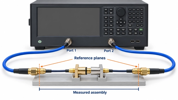
Measure the RF path. Use a VNA with an appropriate measurement calibration. Measure return loss at both ends and insertion loss across the operating band; record transmission phase where required. Define the measurement reference planes and state which cables, fixtures, and PCB launches remain included in the results.
Check the allowed offsets. Repeat the measurements at representative axial, radial, and angular positions from the tolerance budget. Include combinations expected in the equipment. Compare the results with the electrical limits while keeping every test position within the manufacturer’s permitted working range.
Check repeatability after mating. Disconnect and reconnect the assembly for the agreed test sequence. Compare loss, return loss, and phase after each connection. Keep the measurement cables in a consistent position so cable bending does not obscure changes in the connector itself.
Check performance under service conditions. Repeat RF measurements after the required temperature cycling, vibration, or other environmental tests. Monitor during exposure when brief interruptions matter. Record the mounting conditions, offsets, and cable positions so the results can be reproduced.
FAQ
Discussion (0)
Be the first to comment.