What are Ganged RF Connectors? Advantages & Drawbacks Explained

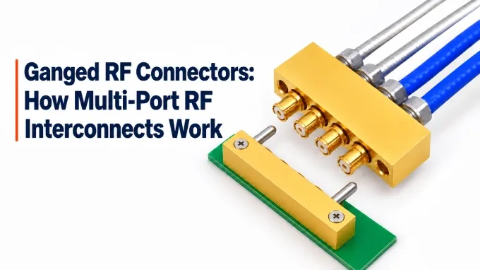
Ganged RF connectors group several coaxial connections in one mechanical assembly so they can be connected together. Each channel retains its own RF signal path; the assembly does not split or combine signals. “Ganged” emphasizes the coordinated mating operation, while “multi-port” describes the multiple connections.
In custom RF cable assemblies, a ganged termination brings several cable ends into a common connector block. This arrangement addresses a practical problem in densely packaged equipment: connecting many RF channels when space and access for individual connectors are limited.
How Do Ganged RF Connectors Work?
Ganged RF connectors use a shared housing to align several coaxial interfaces during mating. Within each channel, the center contact and surrounding outer contact engage their counterparts to complete the connection.
Guide pins, keys, or other alignment features position the two sides before the RF contacts fully engage. Latches, screws, or contact detents hold the connection together, depending on the design. Compact push-on interfaces suit grouped mating because they engage axially without requiring a separate coupling nut to be turned at every port.
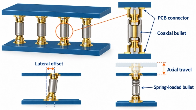
For example, an SMP or SMPM board-to-board connection commonly uses a female-to-female coaxial adapter, called a bullet, between two male PCB connectors. The bullet can tilt within the interfaces to accommodate limited lateral offset. A spring-loaded version compresses to provide additional axial travel when board spacing varies. A detent on one board connector can retain the bullet when the boards separate.
Where Are Multi-Port RF Connectors Used?
Multi-port RF connectors connect multiple channels within radio systems, test equipment, vehicles, and medical devices. Each application places different demands on the interconnect.
Radar and phased-array electronics
Ganged connectors link antenna assemblies, beamforming circuitry, and transmit/receive modules. Where channels operate coherently, the interconnect must meet specified phase and amplitude tolerances.
Multichannel wireless equipment
Radio hardware uses these connectors to route separate RF paths between boards, front-end modules, and antenna connections. Adequate channel isolation must be maintained across the operating band.
RF and semiconductor testing
Multi-port assemblies connect instruments to evaluation boards, test fixtures, or devices under test. Their electrical performance must remain repeatable through the required number of mating cycles.
Modular aerospace and defense equipment
These interconnects connect removable electronic modules to the surrounding equipment. The selected construction must maintain contact under specified shock, vibration, and temperature conditions.
Automotive electronics
Multi-port connectors group coaxial camera links at electronic control units. Signal integrity and secure retention must be maintained under vehicle operating conditions.
Medical equipment
Coaxial assemblies route channels within imaging and patient-monitoring equipment. Some imaging environments require specifically qualified non-magnetic constructions to prevent interference with sensitive equipment.
Advantages of Ganged RF Connectors
Ganged RF connectors simplify assembly when many coaxial paths must fit into limited space. Their main benefits concern packaging, installation, and connection management.
Higher connection density. A common housing can establish tighter, more consistent port spacing than separately mounted connectors. It can also consolidate the hardware used to attach the interfaces to a board or panel.
Fewer mating operations and less need for individual connector access. Several channels connect through one grouped mating operation. Where the design uses shared retention, the installer can secure the assembly without reaching and tightening a separate coupling mechanism at each port.
Fixed channel mapping. A harness that has been assembled and verified preserves the intended cable order, reducing manual connection errors. Appropriate keying can also prevent the block from being inserted in the wrong orientation.
Easier module installation and replacement. Where supported, blind mating lets the RF connections engage as the module is inserted. Technicians can replace the module without individually accessing its RF mating faces.
Drawbacks and Limitations of Ganged RF Connectors
Ganged RF connectors require careful mechanical integration and can make individual channels harder to access or rearrange. Their main limitations concern the complete assembly:
Alignment across all channels. The board and housing mounts must keep every contact within its permitted engagement range. Misalignment at one position can obstruct mating or leave a channel incompletely connected.
Combined mating load. Engaging several contacts simultaneously loads the PCB and mounting hardware. The design may need stiffeners or additional support to prevent board deflection or damage.
Cable-routing clearance. The cable bundle, strain relief, and space needed to withdraw the connector can require considerably more room than the connector footprint alone suggests.
Group disconnection. Accessing or troubleshooting one connection may require unplugging the block, interrupting other RF paths that would otherwise remain connected.
Restricted replacement options. Changing one end of the connection may require changes to the mating half, mounting arrangement, or PCB layout. The RF interface name alone does not establish compatibility.
Implementation-dependent cost. Standard assemblies and custom blocks have different hardware, engineering, and tooling requirements. Any savings in assembly labor must be weighed against the costs of integration, replacement, and servicing.
Individual connectors may be preferable when channel counts are low, cables are frequently rearranged, or technicians need to disconnect and access each channel independently.
Multi-Port RF Connector Configurations and Specifications
Ganged RF connectors are available as cable harnesses, PCB connector blocks, and assemblies installed in equipment housings. Their ratings apply to particular configurations; an individual interface’s specifications do not establish the performance of the complete assembly.
Connection Arrangements, Port Layouts, and Mounting
Available arrangements include:
Cable-to-board: Several cables terminate at a matching PCB connector block.
Board-to-board: Connector assemblies join parallel, coplanar, or perpendicular boards.
Cable-to-cable or panel-mounted: Grouped interfaces connect harnesses or provide connections through an equipment panel.
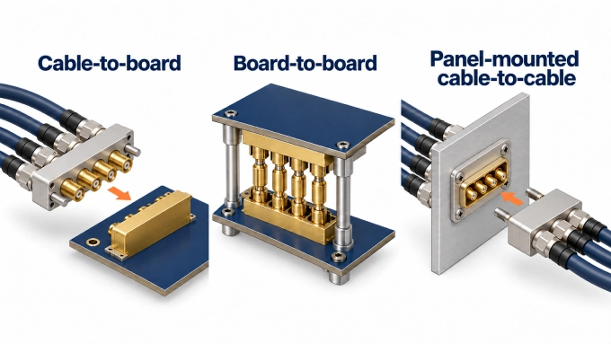
Commercial offerings include 2, 4, 6, 8, and 16 channels in single-row or multi-row layouts. Port spacing varies; one SMPM platform, for example, uses a 3.56 mm pitch. PCB attachment options include surface-mount, through-hole, edge-launch, and solderless compression designs. Straight and right-angle versions provide different board and cable-exit orientations.
RF Interfaces and Mating Compatibility
Standard interfaces used in ganged blocks include SMP, SMPM, SMPS, and MCX. Proprietary multi coax systems offer another approach to packaging high-bandwidth coaxial connectors. Specialized formats include Mini-FAKRA and coaxial inserts in rugged circular or rectangular housings.
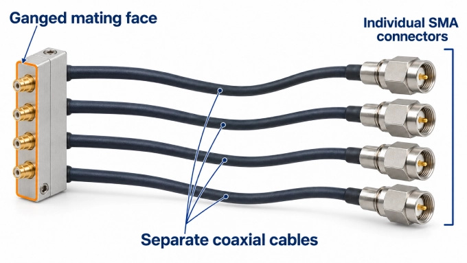
Matching the interface name alone is insufficient: both sides also require compatible contact genders, port layouts, engagement depths, keying, and retention features. Breakout harnesses may carry individual SMA, 2.92 mm, or 2.4 mm connectors at their opposite ends. These cable terminations are separate from the ganged mating face.
Electrical Ratings and RF Performance
Most products use 50 Ω impedance, although 75 Ω MCX versions are also available. Published frequency ratings span both microwave and millimeter-wave designs.
Example construction | Published frequency rating |
Latched cable-to-board family | DC–10 GHz |
Mini-coax test-connector family | DC–20 GHz and DC–40 GHz versions |
Ganged SMPM interfaces | Up to 65 GHz |
Precision multicoax interfaces | Up to 90 GHz |
Electrical specifications also include insertion loss, VSWR and return loss, channel isolation, power handling, and voltage ratings. For example, the mini-coax family above specifies return loss greater than 16 dB through 20 GHz. Some precision cable assemblies offer matching specifications expressed as delay tolerances of ±1 ps or ±2 ps; ganging alone does not provide this matching.
Mating Limits, Durability, and Environmental Ratings
Mechanical specifications cover permitted misalignment, available contact travel, insertion and withdrawal forces, and retention force. Mating life depends on the interface variant: one SMP series lists 100 cycles for full-detent contacts and 1,000 for smooth-bore contacts. The same series publishes an operating temperature range of −65°C to +165°C. These are interface-series figures, rather than universal assembly ratings.
Environmental options include specified shock, vibration, and moisture qualifications, while non-magnetic constructions are available for suitable imaging applications. The applicable qualifications depend on the complete construction.
FAQ
Discussion (0)
Be the first to comment.