Which Coaxial Cable Connector is Used With Higher Bandwidth Signals?

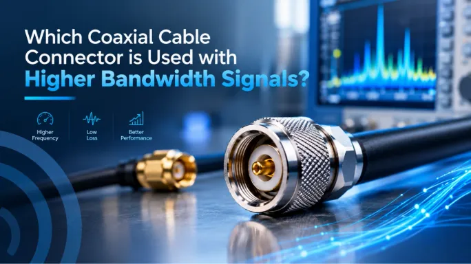
The textbook answer is that for very high-frequency and high-bandwidth RF (radio frequency) signals, SMA (SubMiniature version A) and Type N connectors are most commonly used. SMA connectors handle bandwidths up to 18 GHz or higher, while Type N connectors support up to 11 GHz—and higher in precision grades—with high power handling.
For applications requiring extreme frequency bandwidth, specialized precision connectors are available. Common examples include 2.92 mm connectors rated up to 40 GHz, 2.4 mm connectors up to 50 GHz, 1.85 mm connectors up to 67 GHz, and 1.0 mm connectors reaching approximately 110 GHz. These smaller interfaces maintain impedance and minimize signal reflections at millimeter-wave frequencies.
RF Connector Frequency Range Comparison
The limits listed for these RF connectors are representative manufacturer ranges, not strict universal limits. The actual maximum bandwidth may vary significantly in individual connector designs and the construction of custom RF cable assemblies.
High-Frequency Precision Connectors for Extreme Bandwidth (Microwave & RF)
Precision RF connectors for extremely high-frequency signals range from SMA interfaces, rated to approximately 18 GHz, to 1.0 mm connectors capable of operation up to 110 GHz. These tightly controlled interfaces are primarily used in microwave and millimeter-wave test and measurement, radar, aerospace and semiconductor applications, where low VSWR and repeatable performance are required.
SMA Connectors (Up to 18 GHz - 34 GHz)
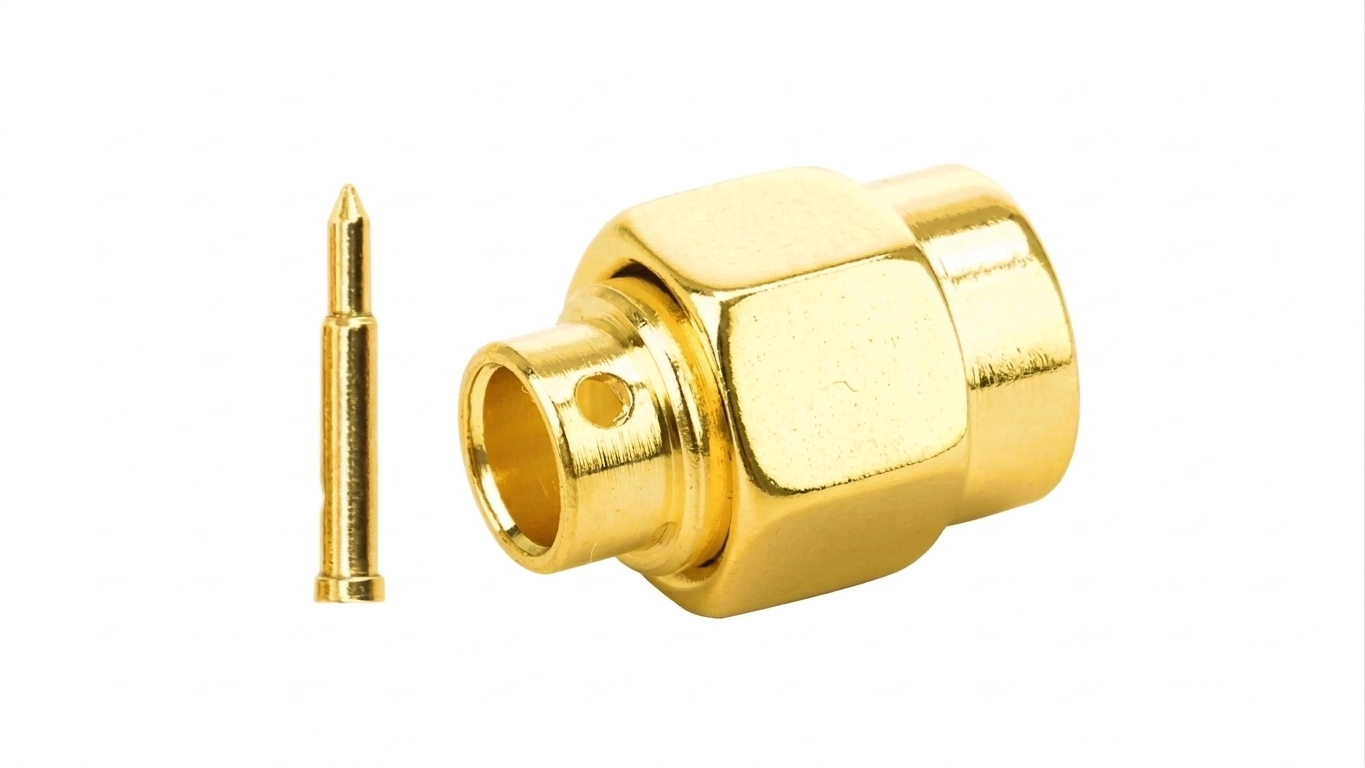
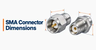
The SMA (SubMiniature version A) connector is the starting point for high-bandwidth precision RF engineering. Commonly paired with RG58 or LMR-400 cables, SMA connectors are ubiquitous in modern IoT modules, GPS systems, and Wi-Fi 6E/7 hardware. A standard SMA handles up to 18 GHz, while precision-machined versions extend to 34 GHz.
3.5 mm RF Connectors (Up to 26.5 GHz)
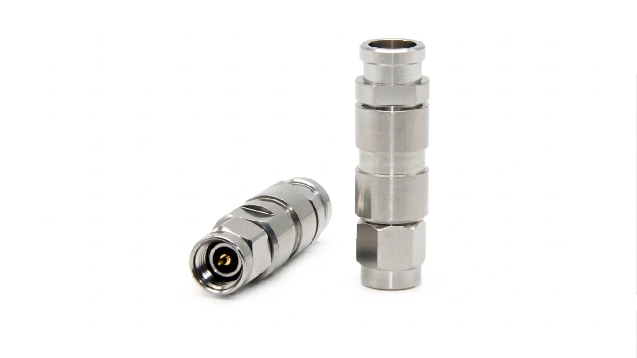
The 3.5 mm connector provides low-reflection performance up to 26.5 GHz. Its air-dielectric interface and stronger mechanical construction give it better repeatability and mating durability than general-purpose SMA connectors.
It mates directly with SMA and 2.92 mm connectors. The interface is primarily used on precision, calibration, and RF test equipment.
2.92 mm (K-Type) & 2.4mm Connectors (Up to 40 GHz - 50 GHz)
As frequencies climb into the K-band, engineers rely on connectors designated by their inner diameter. The 2.92mm connector (also known as the K-Type) pushes bandwidth limits up to 40 GHz. The even smaller 2.4mm connector handles up to 50 GHz. These are heavily used in 5G development and military aerospace technology, utilizing air dielectrics to prevent signal distortion.
1.85 mm (V) Connectors (Up to 67 GHz)
The 1.85 mm connector is specified to 65 GHz under IEC 61169-32, while many commercial V connectors are rated to 67 GHz. This gives the interface coverage across most of the V-band.
It can mate directly with 2.4 mm connectors. Its smaller dimensions provide greater bandwidth but reduce power capacity and make the interface more sensitive to wear, contamination and incorrect mating torque.
The 1.0 mm Connectors (Up to 110 GHz)
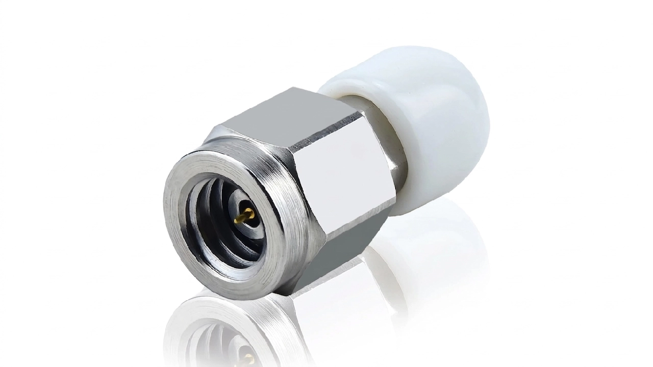
At the absolute cutting-edge of coaxial hardware is the 1.0mm connector. This microscopic connector handles extreme millimeter-wave frequencies up to 110 GHz. Its small center contact requires inspection, cleaning and controlled mating torque because minor damage or contamination can significantly affect return loss at W-band frequencies.
It is used in millimeter-wave metrology, semiconductor characterization, radar development and other applications requiring continuous coaxial coverage beyond 67 GHz.
Why Some RF Connectors Support Higher Frequencies
Some RF connectors support higher frequencies because their smaller internal geometry delays unwanted higher-order modes, while precise impedance control and low-loss dielectric construction reduce reflections and signal loss. However, the usable frequency range of the complete RF path is still limited by its lowest-rated connector, cable, termination, adapter, or PCB launch.
Connector Geometry and Mode-Free Operation
A coaxial connector should carry signals in the transverse electromagnetic (TEM) mode. At higher frequencies, larger interfaces can begin supporting unwanted modes such as TE11, causing resonance and unstable performance. Reducing the connector diameter raises the cutoff frequency at which these modes appear. This is why increasingly smaller interfaces—from SMA and 3.5 mm to 2.92 mm, 2.4 mm, 1.85 mm, and 1.0 mm—support progressively higher frequencies.
Air dielectrics, low-loss support materials, and tightly controlled internal dimensions also help maintain the connector’s characteristic impedance. This reduces reflections, improves return loss, and limits insertion loss across its rated frequency range.
The Complete RF Path Sets the Limit
A connector cannot extend the frequency range of the components around it. For example, a 40 GHz connector attached to an 18 GHz cable or PCB transition still creates an 18 GHz signal path.
Every connector, cable, adapter, termination, and PCB launch must therefore support the required frequency range while maintaining acceptable VSWR, insertion loss, and return loss.
Why Cable Assembly Design Matters at High Frequencies
A high-frequency connector cannot deliver its rated performance if the rest of the cable assembly introduces excessive loss, reflections, or phase instability. The cable type, length, terminations, routing, and adapters must all support the required operating frequency.
Cable type and length: Coaxial cable attenuation increases with frequency and length. A high-frequency connector cannot compensate for an unsuitable cable.
Terminations and adapters: Poor terminations, unnecessary RF adapters, and impedance discontinuities increase insertion loss and signal reflections.
Flexing and routing: Exceeding the minimum bend radius or repeatedly flexing a cable can affect impedance and phase stability. Semi-rigid cable provides greater stability, while flexible coaxial cable is better suited to movement.
Performance verification: VNA testing can verify insertion loss, return loss, VSWR, and phase matching across the complete operating band.
Which High-Bandwidth Connector Should You Choose?
The required frequency range, power level, impedance, mechanical durability, size, and operating environment in various use cases, can help determine which connector is the right fit.
For compact microwave and RF test systems: Choose SMAconnector.
For rugged, outdoor, or higher-power RF systems: Choose N-type connector.
For CATV, cable internet, and satellite systems: Choose F-type connector.
For frequencies beyond standard SMA capabilities: Consider 2.92 mm, 2.4 mm, 1.85 mm, or 1.0 mm precision connectors.
Before making a selection: Check the connector and cable datasheets for frequency rating, impedance, insertion loss, and compatibility.
If standard products cannot meet your frequency, routing, or mechanical requirements, explore our custom RF cable assemblies for application-specific connector, cable, length, and testing options.
FAQ
Discussion (0)
Be the first to comment.