SMA Connector Mating Cycles: What Affects Reliability?

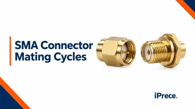
As with any other connectors, SMA connector mating cycles are limited. Repeated mating and unmating can wear an SMA connector’s contact surfaces and disturb its RF interface. Usable life depends on connector construction, handling, service conditions and the RF performance required by the application.
How Many Mating Cycles Can an SMA Connector Withstand?
Many SMA connectors have a published mating-cycle rating of 500 cycles, but the value varies with construction and configuration.
One mating cycle is one complete connection and disconnection. The rating describes endurance against specified acceptance criteria under defined test conditions. The rating does not predict an individual connector’s failure point. Damage or unsuitable service conditions can make it unusable earlier, while reaching the stated count does not imply immediate failure.
When selecting SMA connectors for high-frequency applications, evaluate documented mating durability alongside the required frequency range and RF performance.
What Determines SMA Connector Mating Life?
SMA connector mating life depends on how the complete interface tolerates repeated mechanical contact. Contact geometry, spring force, plating, alignment and cleanliness interact; no single material or construction feature determines durability by itself.
1. Contact Wear and Loss of Contact Pressure
Each mating cycle brings the male center pin into sliding contact with the female socket while seating the outer-conductor surfaces. This wiping action can remove light surface films, but it also produces microscopic abrasion. Over many cycles, wear can alter the contact surfaces and generate fine metallic debris.
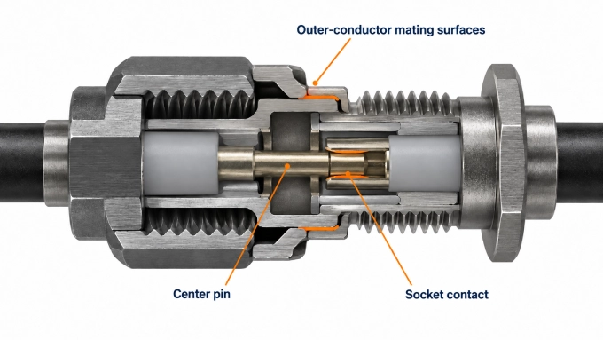
The female center contact relies on elastic spring force to grip the mating pin. Repeated use, excessive insertion force or an oversized or damaged pin can permanently spread or deform its contact fingers. The connector may then develop lower or uneven contact pressure. The male pin can also acquire scratches, plating damage or dimensional deformation that affects every subsequent connection.
2. Plating Thickness, Hardness and Wear-Through
The plating on the electrical contact surfaces reduces oxidation, limits corrosion and helps maintain stable contact behavior. It should be distinguished from the visible finish on the connector body, which may serve different purposes and does not establish the durability of the center contact.
Describing a connector as “gold-plated” is not enough to predict its mating life. The plating alloy, hardness, thickness, underplate and quality of application all affect its resistance to wear. Contact geometry and contact force are equally relevant: insufficient force may produce unstable contact, while excessive force can accelerate abrasion and wear through the finish.
Once the contact plating is breached, the underplate or base metal may become exposed. These materials can be more susceptible to oxidation or corrosion, and worn particles can remain inside the interface. The resulting contact condition may become less stable from one connection to the next.
3. Mating Force, Alignment and Side Loading
Three different mechanical quantities should not be confused:
Insertion force is the force applied while bringing the contacts together.
Contact normal force is the force pressing the mating contact surfaces together.
Coupling torque is applied to the threaded coupling nut to seat and secure the interface.
Angled engagement can scrape the pin or deform the socket before the interface seats. Unsupported cable weight or stiffness can also apply lateral loads to the contacts, retention features or termination. Applying more insertion force cannot correct these conditions and may cause permanent damage in a single mating.
4.Connector Construction and the Condition of Its Mating Partner
Mating durability depends on more than the center contact. The body, coupling nut, threads, dielectric support and contact-retention system must preserve the interface geometry throughout repeated use. Differences in materials, tolerances and mechanical support help explain why SMA connectors with the same nominal interface can have different mating-cycle ratings.
Mating-partner dimensions also matter. An out-of-tolerance SMA contact can damage an otherwise sound counterpart, particularly a compatible precision port. Follow the equipment manufacturer’s inspection and gauging requirements before such connections.
In custom RF cable assemblies, interface wear should be distinguished from damage to the cable termination or contact-retention system, because either condition can make the complete assembly unsuitable for continued use.
5.Contamination and Stresses Between Connections
Dust, metallic debris and residue can obstruct seating or become trapped between contact surfaces. Hard particles may score the plating during mating and transfer to the counterpart. Moisture and corrosive contaminants can also attack exposed underlying material where the finish is porous or worn, leaving films that disrupt consistent contact.
A connector can also deteriorate while it remains fully mated. Vibration, cable movement and thermal expansion can produce repeated microscopic motion between contacting surfaces. This process, known as fretting, can wear the finish and generate debris without adding a complete mating cycle to the service record. The separate guide to microwave connector vibration resistance explains how these in-service movements affect RF interfaces.
How Mechanical Degradation Changes SMA Connector RF Performance
An SMA connector can remain mechanically attached and pass a continuity check even after its RF performance has deteriorated. At microwave frequencies, small changes in contact condition, conductor geometry or interface seating can affect impedance matching, transmitted power and measurement repeatability. The resulting response depends on the type and severity of degradation, the operating frequency and the surrounding signal path.
Impedance Discontinuities: Lower Return Loss and Higher VSWR
An SMA interface is intended to preserve a controlled 50 Ω coaxial geometry through the connection. Mechanical degradation can disturb that transition by changing conductor spacing, displacing the dielectric, deforming a contact or leaving a gap at the mating plane. The affected region then behaves as an impedance discontinuity and reflects part of the incident signal.
Return loss, VSWR and S11 describe this reflection in different forms:
These quantities express the same reflection behavior in different forms.
Contact Degradation and Increased Insertion Loss
Insertion loss describes the reduction in transmitted signal after the connector is introduced into the signal path. For a two-port RF measurement, it is commonly derived from S21, with greater positive insertion loss corresponding to a more negative S21 magnitude.
Mechanical degradation can increase insertion loss through two main mechanisms:
Dissipative loss: unstable or reduced contact pressure can increase contact resistance, converting more RF energy into heat.
Mismatch loss: an impedance discontinuity reflects part of the incident energy instead of allowing it to continue through the connection.
Both mechanisms reduce delivered power, but they are not interchangeable. Return loss measures reflection at an interface; it does not account directly for all energy dissipated within the connector. A connector can therefore show increased insertion loss without a proportional change in return loss, and a poor return-loss result does not by itself establish how much additional dissipative loss has occurred.
A DC continuity test is also insufficient. It can confirm that a conductive path exists, but it cannot verify that the connector maintains its intended impedance and transmission behavior across the microwave operating band.
Poor Reconnection Repeatability and Frequency-Dependent Changes
A worn SMA connector may produce different reflection, transmission or phase results after nominally identical reconnections. This variation adds measurement uncertainty: one trace may meet the limits while the spread between connections exceeds the application’s repeatability allowance. Consistent mechanical contact is therefore essential to repeatable electrical measurements.
Small interface discontinuities can become more consequential at higher frequencies, but the response need not worsen smoothly across the band. Localized reflections, ripple or intermittent changes are possible, and return loss, insertion loss and phase need not change together.
How to Mate and Unmate SMA Connectors Without Accelerating Wear
Correct handling limits unnecessary sliding, twisting and side loading at the interface. The aim is to bring clean, compatible connectors together on the same axis while allowing only the coupling nut to rotate.
Inspect, Align and Engage the Connection
Confirm compatibility. Check connector type, polarity and any equipment-specific mating restrictions.
Inspect both halves. Check for contamination or damage; clean by the approved method when necessary and allow the interface to dry.
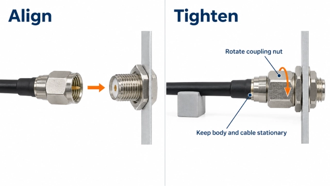
Support and align. Hold the cable so its weight or stiffness does not pull the connectors off-axis.
Engage gently. Start the threads by hand and turn only the coupling nut while keeping the bodies stationary. Stop if engagement binds or requires unexpected force.
Complete the connection. Apply the manufacturer-specified SMA connector torque using the appropriate tool.
Disconnect, Clean and Protect the Interface
Remove RF power and support the assembly.
Release the coupling nut while holding the connector bodies stationary.
Separate axially once the threads are fully disengaged, without twisting or rocking.
Inspect and protect. Clean when necessary using manufacturer-approved materials, allow the interface to dry, and fit clean protective caps. Avoid unapproved lubricants or polishing.
How to Inspect an SMA Connector and Decide When to Replace It
Connector condition should be assessed in three stages: visible and mechanical condition, RF performance and suitability for continued service. Passing one stage does not compensate for failure in another.
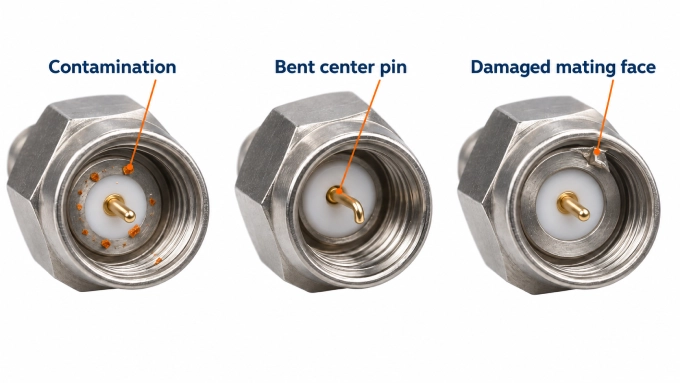
Identify Wear, Damage and Abnormal Engagement
Begin with both halves disconnected and adequately illuminated. Use magnification appropriate to the connector and the application.
Use dimensional gauging where required by the connector or equipment manufacturer, particularly for precision-port connections or suspected contact displacement. Use the correct clean, undamaged gauge and interface-specific limits; do not reshape contacts to make them fit.
Check RF Performance Against a Controlled Baseline
A connector that passes visual inspection may still have an unacceptable impedance discontinuity or unstable contact. RF verification should therefore compare the affected connector or assembly with defined limits under controlled conditions.
Establish mechanical suitability first. Keep damaged or dimensionally suspect connectors away from instrument ports and calibration standards.
Define the limits and baseline. Use applicable product or system requirements and, where available, results from the assembly in known-good condition.
Control the measurement. Use a calibrated VNA with defined reference planes and consistent adapters, cable position, settings and temperature. Account for any cable or fixture contributions within the measured path.
Measure across the operating band. Select one- or two-port characterization based on the DUT and test setup, measuring the relevant reflection, transmission and phase parameters.
Check reconnection variation where appropriate. Remate only mechanically suitable connectors and compare the spread with the application’s allowance. Account for measurement uncertainty when judging results near a limit.
Return the connector to service only when its mechanical condition and required RF performance are acceptable. Persistent electrical failure or unacceptable reconnection variation warrants removal and evaluation or replacement. Record cycle history, inspection findings and RF results, and follow any manufacturer or facility retirement requirement.
FAQ
Discussion (0)
Be the first to comment.