Difference Between VSWR & Return Loss: Understanding Impedance Uniformity in RF Cable Assemblies

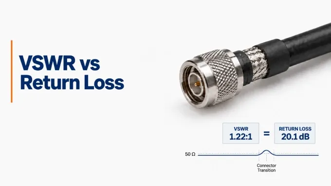
In simple terms, VSWR and return loss both measure signal reflection caused by an impedance mismatch in an RF system, but they do so differently. Return loss quantifies the reflected signal in dB; higher return loss is better. VSWR (Voltage Standing Wave Ratio) expresses the ratio between the highest and lowest voltages in the standing-wave pattern, showing how uneven the voltage becomes along a transmission line when incident and reflected waves overlap. This results from an impedance mismatch as well.
There is also a third way to measure signal reflection: the reflection coefficient. It expresses the ratio of the reflected signal to the incident signal. How these values relate determines their use and which one should matter to you most.
How VSWR and Return Loss Express Signal Reflection Differently
In case of an impedance mismatch, part of the incident RF signal is reflected. VSWR and return loss quantify the signal reflected by impedance mismatches, but express that reflection on different scales:
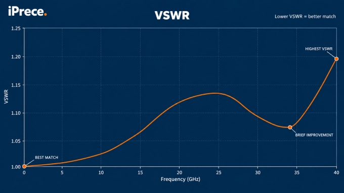
VSWR (Voltage Standing Wave Ratio): VSWR is a unitless ratio that compares the maximum and minimum voltage of the standing-wave pattern created when incident and reflected waves interact along a transmission line. The minimum voltage ratio is always normalized to 1, so it is written as 1.20:1 or 1.50:1. A perfectly matched system would have a VSWR of 1:1, while increasing values indicate progressively greater reflection.
Return loss: Compares the incident signal power with the power reflected toward the source and expresses the difference in decibels. A higher positive return loss means less power is being reflected.Note that VNAs commonly display the corresponding magnitude as a negative value, so 20 dB return loss may appear as −20 dB .
When evaluating a custom RF cable assembly, VSWR expresses the resulting standing-wave severity as a ratio, while return loss expresses the difference between incident and reflected power in decibels. Therefore, better impedance matching produces a lower VSWR but a higher positive return loss.
VSWR vs Return Loss at a Glance
How VSWR, Return Loss, and Reflection Coefficient Relate
As mentioned earlier, the third and fundamental way to measure signal reflection is the reflection coefficient. Reflection coefficient is the ratio of the reflected voltage wave to the incident voltage wave. Its magnitude is always between 0 and 1. A magnitude of 0 means perfect impedance matching and no reflection, while a magnitude of 1 means total reflection, which can occur with either an open circuit or a short circuit. The reflection coefficient is the basis for calculating VSWR and return loss.
To understand how the three values relate, review what happens in the case of an impedance mismatch:
1.An impedance discontinuity produces a reflection
When a signal traveling through a transmission line encounters a different impedance, some energy continues forward while some returns toward the source.
2.The reflection coefficient quantifies the reflection
Represented by gamma , it compares the reflected voltage wave with the incident voltage wave at a specified reference plane.
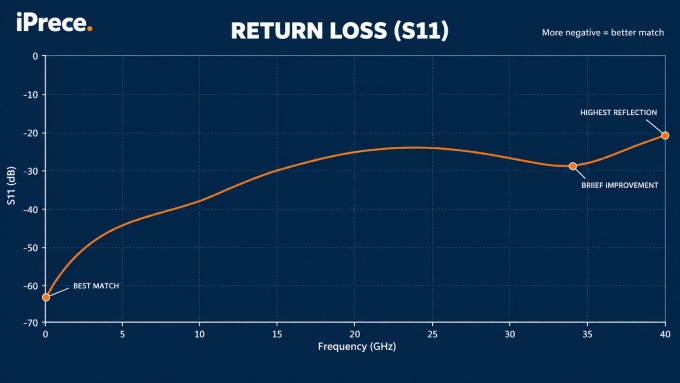
3.VSWR and return loss express the magnitude of on different scales.
VSWR uses a ratio, while return loss uses decibels. Neither adds new reflection information; they are alternative ways of presenting the same magnitude.
VSWR and Return Loss: Which Unit Should You Use?
VSWR, return loss, and reflection coefficient describe the same signal reflection in different ways. The right one depends on what you are doing and how much information you need.
Measurement | Best used for | How to read it |
VSWR | Installing antennas, checking transmitters, and field testing | Lower is better; 1:1 is ideal |
Return loss | Comparing components and checking datasheet requirements | Higher is better; measured in dB |
Reflection coefficient | RF design, impedance matching, and detailed analysis | A magnitude of 0 is ideal; 1 means total reflection |
Use VSWR when you want a simple indication of whether an antenna or transmission line is properly matched. Antenna analyzers and transmitter monitoring systems commonly use VSWR because values such as 1.2:1, 1.5:1, and 2:1 are easy to interpret. It is especially useful for antenna installation, adjustment, and transmitter protection.
Use return loss when comparing the performance of RF components such as antennas, cables, connectors, filters, and amplifiers. Because it uses decibels, return loss is better at showing differences between small reflections. It is commonly found in product specifications, VNA reports, and quality-control requirements.
Use the reflection coefficient when designing or troubleshooting an RF system. Its magnitude indicates how much of the incident voltage wave is reflected, while its phase shows how the reflected wave is shifted. This additional phase information is needed for Smith charts, impedance calculations, and matching-network design.
In practice, you may not need to choose between them. Most modern VNAs and antenna analyzers measure the reflection coefficient and can display the result as reflection coefficient, return loss, or VSWR.
How Do You Calculate VSWR, Return Loss, and Reflection Coefficient?
For a simple boundary between a transmission line with characteristic impedance and a load with impedance , the reflection coefficient is:
A value of =0 means the load and transmission line are perfectly matched, so no signal is reflected. As the magnitude of increases toward 1, the reflection becomes greater.
VSWR is calculated from the magnitude of the reflection coefficient:
A reflection coefficient of zero therefore produces the ideal VSWR of 1:1. Larger reflection coefficients produce progressively higher VSWR values.
Return loss converts the same reflection coefficient into a logarithmic decibel scale:
Because the equation includes a negative sign, a smaller reflection coefficient produces a higher positive return-loss value. A weak reflection may therefore be described by a low VSWR and a high return loss.
The proportion of incident power that is reflected can also be calculated from the reflection coefficient:
Here, reflected power and incident power. For example, if , the reflected-power fraction is , meaning 4% of the incident power is reflected.
These equations describe the relationship between VSWR, return loss, and reflection coefficient cleanly, but the first equation represents a single, simple impedance boundary.
VSWR-to-Return-Loss Conversion Table
The following values in the PDF file, show how VSWR, return loss, reflection coefficient, and reflected power express the same level of signal reflection.
These values should not be assigned universal “good” or “bad” labels. An acceptable VSWR or return-loss limit depends on the operating frequency, system reflection budget, cable and connector capability, measurement uncertainty, and intended application.
Measuring VSWR and Return Loss
VSWR and return loss are normally measured across frequency with a VNA, although return loss can also be measured using a spectrum analyzer, tracking generator, and return-loss bridge. Accurate calibration and proper termination are essential when testing an antenna, filter, or custom RF cable assembly.
Follow our guides to measuring VSWR with a VNA and measuring return loss with a spectrum analyzer. If excessive reflection is detected, the next step is understanding impedance matching and how it can improve power transfer.
FAQ
Discussion (0)
Be the first to comment.