RF Cable Velocity Factor: Formula, Chart, and How to Calculate It

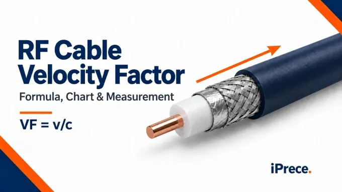
RF cable velocity factor, or , is the ratio of a signal’s propagation velocity inside a cable to the speed of light in a vacuum. It refers to the movement of the electromagnetic wave, whose electric and magnetic fields extend through the dielectric between the conductors. It does not refer to the much slower drift of individual electrons through the conductor.
Velocity factor is defined by the following formula:
Where:
is the cable’s velocity factor.
is the signal propagation velocity inside the cable.
is the speed of light in a vacuum, approximately .
Velocity factor is dimensionless and may be expressed as either a decimal or a percentage. For example, a cable with VF=0.80 or 80% , carries a signal at approximately:
This means that the signal travels through the cable at approximately 80% of the speed of light. Cable datasheets may identify the same value as velocity factor, velocity of propagation, , or .
RF cable velocity factor can be calculated from a known cable length and its measured propagation delay. It can also be estimated from the cable’s effective dielectric constant.
Calculating VF from Cable Length and Propagation Delay
When the physical cable length and one-way propagation delay are known, use:
Where:
is the physical cable length.
is the one-way propagation delay through that length.
is approximately .
The cable length and measured delay must represent the same signal path. If the delay measurement includes test leads, adapters, connectors, or fixture sections outside the measured cable length, their additional delay will affect the calculated velocity factor.
When cable length is measured in meters and delay is measured in nanoseconds, the formula can be written as:
This form avoids manually converting nanoseconds to seconds. When using the standard SI formula, remember that:
Calculating VF from Dielectric Constant
For a low-loss coaxial cable made with nonmagnetic materials, velocity factor can be estimated from the effective relative permittivity of its dielectric structure:
Where is the cable’s effective relative permittivity, commonly called its effective dielectric constant.
For a coaxial cable filled with a uniform solid dielectric, is approximately equal to the material’s relative permittivity, . For foamed, expanded, or air-spaced dielectrics, it represents the combined effect of the base material, air content, foam density, and overall dielectric construction.
The dielectric constant of the solid polymer should therefore not be used directly for a foamed version of that material. Because air has a relative permittivity close to 1, introducing air into the dielectric generally reduces and increases the cable’s velocity factor.
Worked Example: Calculating VF for a 10 m Cable
Suppose a RF cable has a measured one-way propagation delay of . Its velocity factor is:
The cable therefore has a velocity factor of approximately 0.667, or 66.7% . Its propagation velocity is:
This calculation uses one-way propagation delay. A time-domain reflectometer normally measures the round-trip time required for the signal to travel to the far end of the cable and return, so the TDR calculation includes a factor of 2.
Coaxial Cable Velocity Factor Chart
The following coaxial cable velocity factor chart lists published values for several common RF cables. The delay per meter is calculated from each cable’s stated velocity factor using:
These values are suitable for initial timing and cable-length calculations. For custom RF cable assemblies or precision applications, use the datasheet value for the exact cable model or measure the installed cable.
A higher velocity factor produces a shorter propagation delay for the same physical cable length. For example, a signal takes approximately to travel one meter through the listed RG-58 cable but approximately through LMR-400.
These values apply to the identified products. A generic designation such as RG-58 or RG-6 does not guarantee an identical velocity factor across every manufacturer, construction, or cable variant.
The delay values in the table are calculated consistently from the displayed velocity factors. Manufacturer datasheets may list slightly different delay figures because VF and delay are sometimes published as separately rounded nominal values.
What Affects RF Cable Velocity Factor?
RF cable velocity factor is determined mainly by the effective permittivity of the material and structure between the inner and outer conductors. Temperature, frequency, and manufacturing variation can also affect the actual propagation velocity.
Dielectric Material and Construction
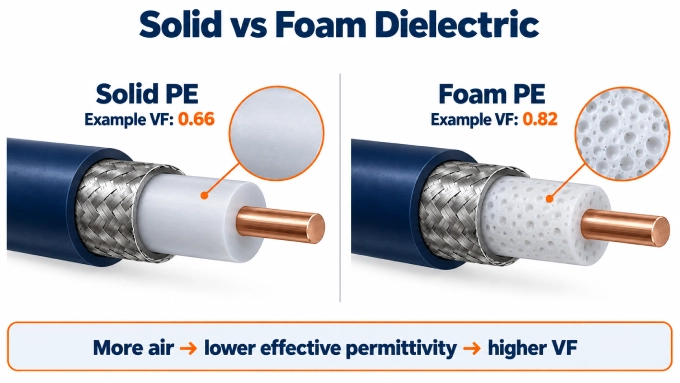
The dielectric has the greatest influence on the velocity factor. For a low-loss cable with nonmagnetic materials, the relationship is:
As the effective relative permittivity, , increases, the signal travels more slowly and (VF) decreases.
The effective permittivity depends on three main aspects of the dielectric:
Base material: Solid polyethylene and PTFE have higher effective permittivity than air, so signals travel more slowly through them.
Dielectric construction: Foaming, expanding, or air-spacing the material introduces air with a relative permittivity close to 1. This lowers and generally increases .
Manufacturing consistency: Foam density, air content, material formulation, and extrusion consistency can vary between products. Two foam-polyethylene cables may therefore have different velocity factors.
Cable diameter and conductor spacing do not directly determine velocity factor in an ideal coaxial cable filled with a uniform dielectric. In a real cable, geometry matters only when it changes the dielectric structure or the distribution of the electromagnetic field across different materials.
These dimensions also help determine coaxial cable characteristic impedance, but impedance and velocity factor are separate specifications. Two cables can both have an impedance of while using different dielectrics and having different propagation velocities.
Temperature
Temperature can affect cable delay in two distinct ways.
First, it may change the dielectric’s permittivity, density, or mechanical compression. A change in effective permittivity changes the signal velocity and therefore the cable’s velocity factor.
Second, thermal expansion or contraction changes the cable’s physical length. A longer cable produces more total propagation delay even if its velocity factor remains unchanged. A measured change in delay with temperature may therefore result from a change in VF, a change in physical length, or a combination of both.
The size and direction of these effects depend on the dielectric, conductors, shielding structure, and manufacturing method. There is no single temperature coefficient that applies to all RF cables.
Frequency Dependence
Datasheets commonly provide one nominal velocity factor for the cable’s operating range, which is usually sufficient for general delay and length calculations. In a real cable, however, dielectric dispersion and conductor effects can cause propagation velocity to vary somewhat with frequency.
How to Measure Coaxial Cable Velocity Factor
Velocity factor is measured by comparing a cable’s known physical length with its propagation time. A TDR obtains this time from the round-trip reflection at the far end, while a VNA can measure the one-way transmission delay through the cable.
Measuring Velocity Factor with a TDR
A TDR sends a fast electrical step into the cable and displays the returning reflections. With the far end open or shorted, the signal travels the cable length twice: once toward the termination and once back to the instrument.
Follow these steps to measure coaxial cable velocity factor:
Measure the physical cable length. Measure between the same endpoints that will define the TDR measurement path. For a connectorized cable, decide whether the result should represent only the cable body or the complete assembly.
Set the near-end reference plane. Connect the cable to the TDR and place the time reference at the cable input. Calibrate or compensate for any test leads and adapters that remain before this point.
Leave the far end open or shorted. Either condition creates a strong reflection. An open circuit normally produces a positive reflection, while a short circuit produces a negative one. A matched termination should not be used because it absorbs most of the incident signal.
Measure the round-trip time. Place one cursor at the near-end reference and another at the start of the far-end reflection. The interval between them, \Delta t , is the time required for the signal to travel to the end of the cable and return.
Calculate velocity factor. Because the measured signal covers twice the physical cable length, use:
Where:
is the one-way physical cable length.
is the measured round-trip time.
is approximately .
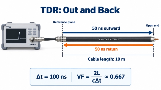
Finally, compare the calculated VF with the expected range for the cable’s dielectric construction. If the result appears unreasonable, check the reference plane, reflection selection, cable length, and time measurement.
Measuring Velocity Factor with a VNA
A vector network analyzer can determine effective velocity factor from the one-way transmission delay through a cable:
Perform a two-port calibration so the reference planes are located at the cable connections.
Connect the cable between the two calibrated ports and measure across the relevant frequency range.
Display the transmission group delay and record the delay, , at the required frequency or across the required band.
Calculate the effective velocity factor from the cable’s known physical length:
A VNA derives group delay from the slope of transmission phase with frequency:
For a sufficiently nondispersive coaxial cable, group delay is approximately constant and closely represents its propagation delay. If the cable is dispersive, the measured delay and calculated effective VF may vary with frequency. See RF group delay for a more detailed explanation of the measurement and its interpretation.
Any connectors, adapters, or fixture sections between the calibrated reference planes contribute to the measured delay. The physical length used in the VF calculation must represent the same path.
How to Use Velocity Factor to Calculate Signal Propagation Time
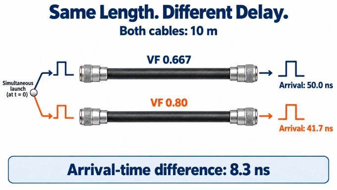
Once the cable’s velocity factor and physical length are known, its one-way RF signal propagation time can be calculated using:
Where:
is the one-way propagation time.
is the physical cable length.
is the cable’s velocity factor.
is approximately .
For a cable length in meters and delay in nanoseconds, the formula becomes:
The delay per meter can therefore be calculated as:
A higher VF produces less delay for the same physical length. Increasing the cable length increases total delay in direct proportion but does not inherently change the cable’s velocity factor.
FAQ
Discussion (0)
Be the first to comment.