What Are RP-SMA Connectors? And Why Do They Even Exist?

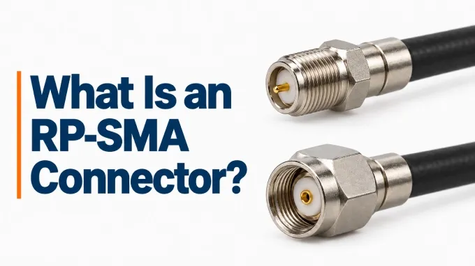
An RP-SMA connector is the reverse-polarity version of the standard sma connector. It retains the same threaded coupling and nominal 50 Ω impedance, but exchanges the pin and socket arrangements between the plug and jack. “Reverse polarity” refers only to the mating contacts: the center conductor still connects through the center contacts, and the shield connects through the outer contacts. The connector does not reverse the electrical polarity of the RF signal.
Why Do RP-SMA Connectors Exist?
RP-SMA was introduced to discourage users from attaching antennas outside a wireless device’s intended configuration. In the United States, FCC Part 15.203 recognizes permanently attached antennas or unique antenna couplings as ways to restrict antenna substitution. Reversing the SMA center contacts created an interface that could not directly mate with standard SMA antenna connections. The rule did not specifically require RP-SMA. The interface subsequently became established in wireless equipment, supported by a broad range of matching connectors, cables, and adapters.
RP-SMA vs SMA Connectors
SMA and RP-SMA retain the same threaded coupling but use opposite center-contact arrangements in their corresponding plugs and jacks. The male/plug and female/jack names refer to the coupling bodies, so a connector’s gender does not identify its center contact unless the interface family is also known.
Neither interface is inherently better for RF performance. A nominal 50 Ω designation does not guarantee identical reflections or insertion loss. Contact dimensions, dielectric supports, and the transition into the cable determine how closely the connection maintains the intended impedance.
Local impedance discontinuities reflect some RF energy, while conductor and dielectric losses dissipate part of it. Both effects vary with frequency and depend on the connector’s design and termination. Compare the selected parts’ VSWR or return loss and insertion loss across the operating band under comparable conditions.
Characteristic | Standard SMA | RP-SMA |
Male / plug center contact | Pin | Socket |
Female / jack center contact | Socket | Pin |
Coupling arrangement | SMA threaded coupling | Same coupling arrangement |
Nominal impedance | 50 Ω | 50 Ω |
Frequency and RF ratings | Part-specific | Part-specific |
How Do You Tell SMA vs RP-SMA Connectors Apart?
For both SMA and RP-SMA, the mating coupling threads determine gender, regardless of whether the center contact is a pin or socket. Identify male or female first, then use the center contact to distinguish standard SMA from RP-SMA.
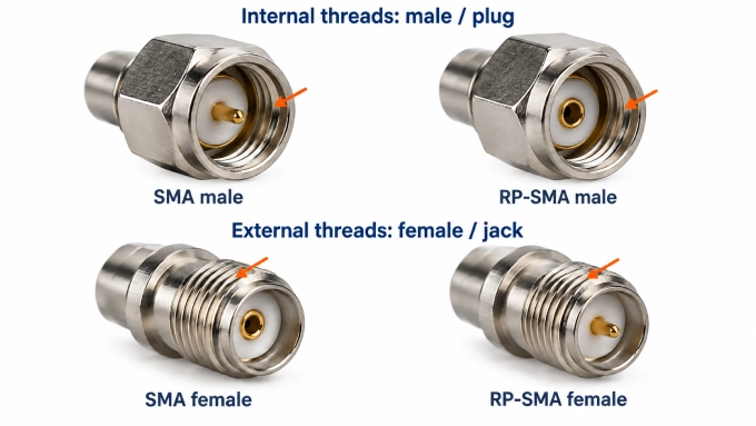
Identify the gender from the threads. Internal threads inside the coupling nut indicate male/plug; external mating threads indicate female/jack. Inspect the coupling threads, not a separate panel-mounting thread.
Identify the interface family. Inspect the center pin or socket and match it to the established gender using the comparison table above.
Confirm the complete designation. Verify both the interface family and gender against the manufacturer’s drawing.
Do not rely on the equipment type, connector finish, or an ambiguous seller’s description.
Is RP-SMA Compatible With SMA Connectors?
Standard SMA and RP-SMA connectors are not directly compatible. Each family uses its own male-to-female mating pair. An SMA male against an RP-SMA female creates pin-to-pin interference and risks contact damage if forced. An RP-SMA male against an SMA female leaves two sockets; the shells may tighten without forming the intended center-contact connection.
A purpose-built SMA-to-RP-SMA adapter or cable assembly can connect equipment that uses different interfaces. Each end must present the correct family and gender to its mating port, and the adapter or assembly must meet the application’s RF requirements.
RP-SMA Connector Applications
RP-SMA connectors commonly provide detachable antenna connections on wireless equipment, particularly Wi-Fi hardware. Typical examples include:
Wi-Fi routers and access points: Many models use RP-SMA for external antennas, sometimes providing separate ports for multiple antennas.
Wireless network adapters: Some USB Wi-Fi adapters and PCIe wireless cards use RP-SMA ports for removable antennas.
Embedded and ISM-band equipment: Selected embedded radios and IoT gateways provide RP-SMA antenna ports, including equipment operating in ISM bands.
Devices in the same category can use different interfaces, so confirm the actual port before choosing a connector.
RP-SMA Cable Applications
An RP-SMA cable assembly has an RP-SMA connector at one or both ends; the opposite end may use another interface. For a custom RF cable assembly, specify the cable type, length, routing requirements, and interfaces at both ends. RP-SMA identifies the connector interface, not a separate coaxial-cable technology.
Equipment-to-antenna leads connect a radio port to an external antenna.
Antenna extensions provide additional reach between an existing antenna connection and the antenna.
Module-to-panel pigtails connect a module’s RF port to an enclosure-mounted RP-SMA connector.
An antenna extension introduces cable and connector loss in both transmission and reception. Evaluate its insertion loss across the operating band, since cable attenuation generally increases with frequency. Assess whether the improved antenna position offsets the added loss, and keep the run as short as the required placement allows.
RP-SMA Connector Specs & Configuration
An RP-SMA connector’s complete specification includes its mounting, body orientation, termination, performance limits, and dimensions.
Mounting, Orientation, and Termination
These independent attributes can coexist in one connector; their names do not establish interface polarity.
Mounting: Connectors attach to a cable, PCB, or panel. Bulkhead versions mount through a panel.
Orientation: Bodies may be straight or right-angle. The SMA female right-angle connector guide illustrates this body format for standard SMA; an RP-SMA version has a different center-contact arrangement.
Termination: Cable attachments may use crimping, soldering, or both. A crimp connector may still require its center contact to be soldered.
Electrical, Mechanical, and Environmental Ratings
RP-SMA connectors are available with different electrical, mechanical, and environmental capabilities. These examples describe different products, not one combined specification or the full market range. Manufacturers offer different ratings and configurations.
Representative published specifications include:
Parameter | Available ratings |
Operating frequency | DC to 6 GHz, 7 GHz, 12.4 GHz, or 18 GHz. |
Working and test voltage | examples include 166 V RMS and 480 V RMS. Dielectric-withstand test ratings include 500 V RMS and 1,000 V RMS. |
RF power handling | Variable; dependant on intended operating frequency and conditions. |
Mating torque | 0.5 N·m and 0.8–1.1 N·m for different constructions. |
Mating durability | Minimum ratings of 100 or 500 mating cycles, depending on the design. |
Operating temperature | −65 °C to +165 °C. |
Environmental sealing | Options include IP67-rated bulkhead versions. |
RP-SMA Connector Dimensions
RP-SMA commonly uses a 1/4-36 UNS coupling thread. Its nominal major diameter is 6.35 mm; this is not the connector’s overall body diameter.
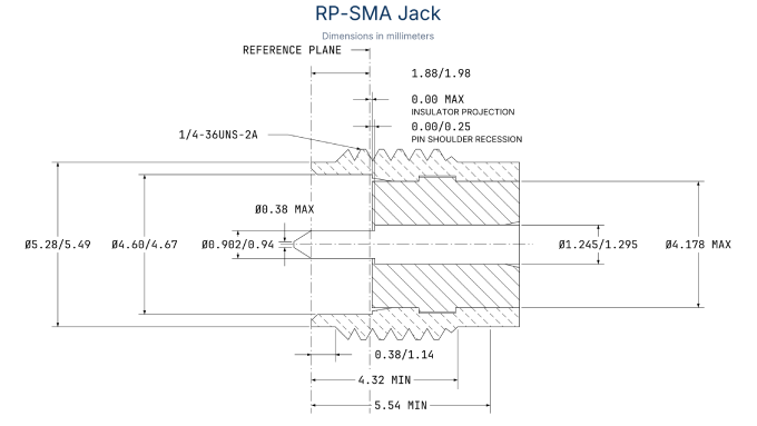
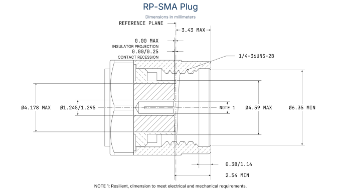
Use the appropriate RP-SMA interface drawing to check center-contact dimensions and mating reference planes. Body length, wrench clearance, panel cutout, and PCB footprint depend on the individual part, so use its product drawing for installation dimensions. The SMA Connector Dimensions guide provides further detail on mating-interface geometry and tolerances.
How Do You Choose Between SMA and RP-SMA?
When replacing or extending an existing connection, match the equipment’s interface. For a new design, choose the family that fits the intended radios, antennas, and accessories while meeting the product’s requirements.
Family: SMA or RP-SMA. Confirm the designation in the equipment documentation or design specification. For new hardware, check that suitable mating parts are available throughout the intended system.
Gender: plug or jack. Use the earlier identification procedure to establish whether the mating port is a plug or jack, then select its complementary interface. Specify family and gender together when identifying the required part.
Impedance and operating frequency. Confirm the system impedance and check the selected part’s RF ratings across the complete operating band. For antenna connections, also verify the antenna’s frequency coverage, polarization, and suitability for the equipment.
Coax and termination. Match the connector to the exact cable construction and the manufacturer’s specified attachment method. Define the assembly’s opposite-end interface separately, since each end must match the component it connects to.
Mechanical fit and operating conditions. Check mounting, orientation, panel or PCB fit, and clearance for mating, tightening, and cable routing against the drawing. For panel mounting, the SMA female bulkhead connector guide explains the mounting format for standard SMA; confirm the RP-SMA interface separately. Verify that temperature and sealing ratings suit the environment and that durability supports the expected number of connection cycles.
Example: Connecting an RP-SMA Radio to an N-Type Antenna
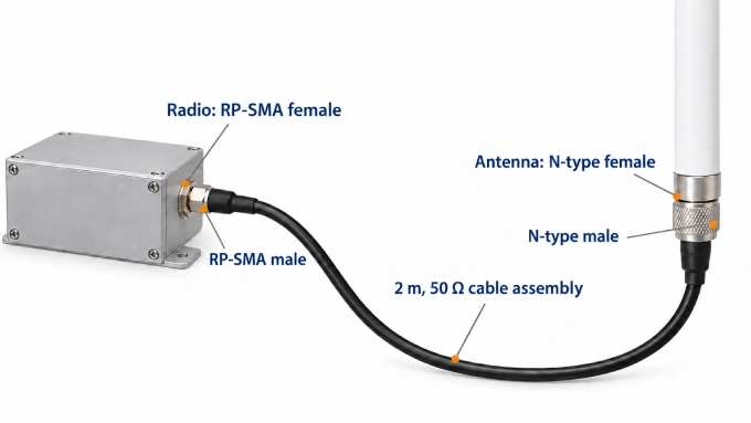
Suppose a 50 Ω radio operating in the 2.4 GHz band needs a 2 m cable assembly to reach an external antenna. The equipment ports determine the required connector at each end:
Connection point | Equipment interface | Required cable connector |
Radio | RP-SMA female | RP-SMA male |
Antenna | 50 Ω N-type female | 50 Ω N-type male |
The assembly therefore combines two connector families, with each end matching its own mating port. For this type of connection, explore our N-Type to RP-SMA cable assembly builder to configure an assembly that matches both equipment interfaces.
For an illustrative electrical check, assume the project permits a maximum insertion loss of 1 dB and a maximum VSWR of 1.5:1 across the radio’s operating band. A candidate assembly specified for no more than 0.8 dB insertion loss and 1.3:1 VSWR throughout that band would meet those limits. Cable attenuation alone would not establish this result; the specification must cover the finished assembly, including both terminations.
Next, confirm that both connector versions support the selected cable construction and attachment method. Check that the cable can follow the required route without exceeding its bend limits or placing excessive strain on the radio port. Allow clearance for tightening both connectors, and provide suitable sealing wherever the connection is exposed to weather.
FAQ
Discussion (0)
Be the first to comment.