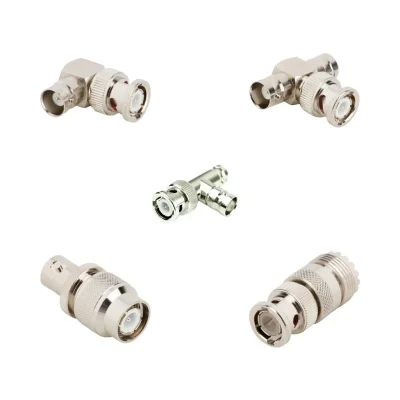

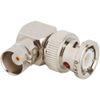
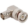
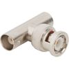
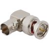
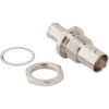
BNC Adapter Specifications
iPrece BNC adapters include 50 Ω and 75 Ω models in straight, right-angle, tee, and panel-mount configurations. The tables below summarize available ratings and construction options; exact specifications depend on the selected part.
RF and Electrical Specifications
Specification | Available Ratings / Options |
Nominal impedance | 50 Ω / 75 Ω |
Maximum frequency ratings | 0.3–12 GHz, depending on model |
Common maximum frequencies | 2–4 GHz |
VSWR | Contact engineering |
Insertion loss | Contact engineering |
Adapter Interfaces and Frequency Ratings
Adapter Interface | Impedance | Maximum Frequency Ratings |
BNC to BNC | 50 Ω / 75 Ω | Commonly 2–4 GHz; selected 75 Ω models: 12 GHz |
BNC to HD-BNC | 75 Ω | 3–4 GHz; selected models: 12 GHz |
BNC to MCX | 50 Ω / 75 Ω | 4–6 GHz |
BNC to TNC / RP-TNC | 50 Ω | 4 GHz |
BNC to RP-BNC / SMC | 50 Ω | 4 GHz |
BNC to AMC | 50 Ω | 6 GHz |
BNC to UHF | 50 Ω | 0.3–4 GHz |
BNC to FME | 50 Ω | 1 GHz |
Mechanical and Mounting Options
Specification | Available Options |
Adapter type | In-series / between-series |
Two-port gender combinations | Plug–plug / plug–jack / jack–jack |
Body orientation | Straight / 90° / tee |
Panel mounting | Bulkhead / 4-hole flange |
Push-on BNC versions | Selected models |
Approximate unit weight | 4–32 g |
Materials and Finishes
Component | Available Materials / Finishes |
Body material | Brass; selected zinc diecast or phosphor bronze |
Body finish | Nickel, gold, silver, tin/nickel |
Contact material | Phosphor bronze, beryllium copper, brass |
Contact finish | Gold / silver |
Insulator material | PTFE, Delrin, PPO, styrene copolymer |
Operating Temperature and Environmental Options
Specification | Available Ratings / Options |
Common operating temperature | −40 °C to +85 °C |
Extended-temperature models | −65 °C to +165 °C |
Ingress protection | IP67 on selected models |
Hermetic construction | Selected bulkhead model |
Isolated mounting options | Selected models |
Temperature, sealing, and isolation options are model-specific. Confirm the selected part’s ratings and any required installation conditions before ordering.
BNC Adapter Types and Configurations
BNC adapter types can be classified by connector interface, geometry, and mounting configuration. The appropriate choice depends on whether the connection must extend an existing BNC interface or transition between different coaxial connector families.
In-Series BNC Adapters
In-series BNC adapters connect two BNC interfaces. They are used when both sides of the connection use BNC connectors but differ in gender, orientation, or mounting requirements.
Selected configurations include:
BNC plug-to-BNC jack
BNC jack-to-BNC jack
Straight and right-angle configurations
Bulkhead-mounted configurations
Tee adapters for branching a coaxial connection
Selected isolated bulkhead configurations
Between-Series BNC Adapters
Between-series adapters provide a transition between BNC and another coaxial connector interface. They are used when equipment, cables, or test instruments have different connector families.
Selected configurations include BNC-to-MCX, BNC-to-TNC, and BNC-to-UHF transitions. Their electrical ratings depend on the specific interface combination and adapter design.
An RF to BNC adapter provides a transition from a specified RF connector interface to a BNC connection. Since RF is a general term rather than a specific connector family, identify the exact interface on the opposite end, such as MCX, TNC, or UHF. Connector gender, impedance, frequency range, and RF performance should be verified before selecting the adapter.
Impedance: 50 Ω and 75 Ω BNC Adapters
Impedance is one of the most important selection criteria for a BNC coaxial adapter. The adapter should match the nominal impedance of the connected cable and equipment to maintain the intended signal path and minimize reflections caused by impedance discontinuities.
50 Ω BNC Adapters
50 Ω BNC adapters are used in RF test systems, instrumentation, communication equipment, and other applications designed around 50 Ω coaxial interfaces.
Selected 50 Ω configurations in the iPrece product range include BNC-to-BNC and between-series transitions such as BNC-to-MCX and BNC-to-TNC. Selected configurations support frequency ranges up to 4 GHz, depending on the adapter type.
75 Ω BNC Adapters
75 Ω BNC adapters are used in broadcast, video, and coaxial distribution systems designed around 75 Ω interfaces.
When selecting a 75 ohm BNC adapter, verify that the adapter, cable, and connected equipment all support 75 Ω operation. This is particularly important in broadcast, video, and coaxial distribution systems, where impedance mismatches can increase signal reflections and affect transmission performance.
Selected 75 Ω BNC-to-BNC configurations have frequency ratings up to 2 GHz or 4 GHz, while a selected 12 GHz-optimized configuration is also available. These ratings apply to specific configurations and should not be generalized to every 75 Ω BNC adapter.
Selection factor | 50 Ω configuration | 75 Ω configuration |
Typical system use | RF instrumentation and communication systems | Broadcast, video, and coaxial distribution |
Nominal impedance | 50 Ω | 75 Ω |
Frequency capability | Selected configurations up to 4 GHz | Selected configurations up to 2 GHz, 4 GHz, or 12 GHz |
Main selection requirement | Match the 50 Ω signal path | Match the 75 Ω signal path |
Applications of BNC Coaxial Adapters
BNC adapters are used across systems that require coaxial connections between equipment, cables, and test interfaces.
Common application areas include:
RF test and measurement: Connecting RF instruments, test cables, and equipment with BNC interfaces.
Broadcast and video systems: Supporting 75 Ω coaxial connections where the complete signal path is designed for the required impedance and frequency.
Communication equipment: Providing coaxial transitions between BNC and other specified RF connector interfaces.
Laboratory and production testing: Adapting test setups to different connector genders or interface families.
Panel-mounted equipment: Providing an accessible BNC connection through an enclosure or instrument panel.
Coaxial signal distribution: Supporting selected branching and interconnection arrangements using BNC tee adapters.
How to Select the Right BNC Adapter
Choosing the right adapter requires checking the connector interface, impedance, operating frequency, mechanical design, and environmental conditions together.
1. Identify Both Connector Interfaces
Determine the connector type and gender on each side of the connection. For an in-series adapter, confirm the required BNC plug and jack arrangement. For a between-series adapter, identify the second connector family precisely, such as MCX, TNC, or UHF.
2. Match the System Impedance
Confirm whether the application uses a 50 Ω or 75 Ω signal path. The adapter, cable, and connected equipment should have compatible nominal impedance. Do not select an adapter based only on the fact that both mating interfaces are BNC.
3. Verify the Operating Frequency
Check the maximum operating frequency of the exact adapter configuration. The rating should cover the full frequency range of the application, with suitable performance across the required band.
4. Review RF Performance Requirements
For applications with strict signal-integrity requirements, review VSWR, insertion loss, and S-parameter data over the operating frequency range. Request the relevant test information when numerical limits are not available on the product page.
5. Choose the Appropriate Mechanical Configuration
Select a straight, right-angle, tee, or bulkhead arrangement based on cable routing, panel thickness, mounting space, and access requirements. Confirm whether a standard bayonet or selected push-on coupling is required.
6. Check Materials and Environmental Limits
Review body and contact materials, plating, dielectric construction, and operating temperature range. For demanding installations, also verify any required isolation, sealing, or environmental qualification.
7. Confirm Specifications Before Ordering
Before placing an order, provide the required connector combination, impedance, frequency range, gender, mounting configuration, and any RF performance or environmental requirements. This helps ensure that the selected BNC adapter is suitable for the intended system.
Quality and Standards
iPrece supports BNC adapter procurement with an ISO 9001:2015-certified quality management system, mechanical and electrical verification, and lot traceability. These controls provide a documented basis for evaluating product conformity and supporting repeat orders.
RF performance verification: Calibrated vector network analyzers support verification of parameters such as VSWR and insertion loss against the applicable product requirements.
Mechanical validation: Components undergo mechanical and electrical checks before shipment to verify conformity with their specified requirements.
Compliance documentation: RoHS and REACH documentation, relevant technical data, and compliance certificates can be requested for the selected adapter to support procurement and customer approval.
For projects with specific interface standards, environmental qualifications, or acceptance criteria, iPrece provides direct access to RF engineering support. Discuss these requirements during quotation so the selected BNC adapter and supporting documentation can be reviewed against your project’s needs.