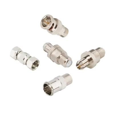

F-Type Adapter Specifications
iPrece’s F-Type adapter range includes in-series and between-series configurations for coaxial RF connections. Standard F-Type interfaces are typically used in 75 Ω systems, while selected between-series adapters provide 50 Ω transitions to other connector families. Available designs include straight, right-angle, bulkhead, threaded, and selected push-on configurations. Frequency ratings, materials, and mechanical features depend on the exact adapter.
Electrical Performance
Specification | Available Ratings / Options |
Impedance | 75 Ω standard configurations; selected 50 Ω between-series configurations |
Maximum frequency | Up to 2 GHz with selected models rated to 3 GHz. |
Standard F-Type-to-F-Type frequency ratings | DC–1 GHz; selected configurations up to DC–2 GHz |
F-Type-to-BNC | Selected 75 Ω configurations rated up to DC–2 GHz |
F-Type-to-SMB | Selected 50 Ω configuration rated up to DC–2 GHz |
G-Type-to-F-Type | Selected 75 Ω configuration rated up to DC–1 GHz |
VSWR / return loss | Confirm the specified limits for the selected adapter and operating band |
Insertion loss | Confirm the specified or measured value for the selected adapter |
Coupling mechanism | Threaded; selected push-on configurations |
RF verification | iPrece identifies the F-Type adapter series as VNA-tested; confirm measurement coverage and documentation for the selected configuration |
The maximum frequency depends on the adapter type and interface combination. Standard F-Type-to-F-Type configurations include models rated to 1 GHz, while selected versions support up to 2 GHz. The same 2 GHz upper limit applies to selected F-Type-to-BNC and F-Type-to-SMB configurations, but their impedance and connector interfaces differ.
Adapter Interface | Listed Impedance | Maximum Frequency |
F-type to F-type | 75 Ω | 1 or 2 GHz |
F-type to BNC | 50 or 75 Ω | 1–2 GHz; selected 75 Ω model to 3 GHz |
F-type to SMB | 50 or 75 Ω | 2 GHz |
F-type to G-type | 75 Ω | 1 GHz |
Gender, Orientation, and Mounting
Specification | Available Options / Requirements |
Adapter format | In-series; between-series |
In-series interface | F-Type to F-Type |
Between-series interfaces | BNC to F-Type; F-Type to SMB; G-Type to F-Type |
Connector gender | Plug and jack combinations, depending on the selected adapter |
Body orientation | Straight; selected right-angle configurations |
Panel mounting | Selected bulkhead configurations |
Coupling mechanism | Threaded; selected push-on F-Type versions |
Opposite-end coupling | Depends on the connector family used at the other end |
Standard F-Type interfaces use screw coupling. This threaded connection provides mechanical retention and is commonly used in coaxial distribution systems. Selected push-on versions offer faster mating and unmating in applications with frequent connection cycles.
The coupling mechanism must be checked at both ends of a between-series adapter. For example, a BNC-to-F-Type adapter combines the BNC bayonet interface with the threaded F-Type interface, while an F-Type-to-SMB configuration connects two different mating systems.
For panel-mounted installations, confirm the required bulkhead arrangement, panel thickness, mounting dimensions, and connector access. Bulkhead mounting is available only on selected configurations and should not be assumed for the entire adapter range.
Materials and Finishes
Component | Available Materials / Finishes |
Body material | Brass |
Body finish | Nickel; tin; gold |
Contact material | Beryllium copper; brass; phosphor bronze |
Contact finish | Gold; bright tin; tin; nickel |
Insulator material | PTFE; Delrin; polypropylene |
Magnetic properties | The product family contains magnetic materials |
PFAS status | Contains PFAS on selected configurations; verify the exact variant |
Material and finish options vary by adapter configuration. Brass bodies are used across the documented range, while contact materials and plating depend on the specific design.
The insulator material is also configuration-dependent. PTFE, Delrin, and polypropylene are used in different variants.
Operating Temperature and Environmental Considerations
Specification | Available Ratings / Options |
Maximum available temperature range | Selected configurations rated from −65 °C to +165 °C |
Other temperature grades | −55 °C to +85 °C; −40 °C to +85 °C |
Environmental sealing | No general IP rating should be assumed for the adapter family |
Material compliance | Request applicable RoHS and REACH documentation for the selected configuration |
Magnetic properties | The family contains magnetic materials |
Temperature ratings depend on the selected adapter and its construction. Do not apply the highest temperature range to every F-Type adapter. Similarly, the presence of a threaded interface does not establish environmental sealing or outdoor suitability.
How to Select the Right F-Type Adapter
Start by identifying the two connector interfaces that need to be connected. An in-series F-Type adapter connects two F-Type interfaces, while a between-series F-Type adapter provides a transition to another coaxial connector family.
Before selecting an F-type adapter, verify:
Connector series and gender: Identify the connector interface at both ends and confirm whether each side requires a plug or jack. Check the center-contact arrangement and mating geometry.
Impedance: Determine whether the application requires a standard 75 Ω F-Type connection or a documented 50 Ω between-series transition. Match the adapter to the connected signal path.
Frequency rating: Verify the operating range of the exact adapter. Some F-Type-to-F-Type configurations are rated to 1 GHz, while selected variants reach 2 GHz.
RF performance: Check VSWR or return loss and insertion loss across the required band. Obtain model-specific limits where these parameters are important to system performance.
Adapter type: Decide whether an in-series F-Type connection or a between-series transition is required.
Orientation and mounting: Choose a straight or right-angle body according to installation clearance and cable routing. Confirm whether a bulkhead configuration is required.
Coupling mechanism: Determine whether threaded or push-on mating is appropriate for the connection frequency and mechanical requirements.
Material and environmental suitability: Check the body, contact, and dielectric materials against temperature, corrosion, magnetic-field, and substance-control requirements.
A connector that physically mates does not automatically provide the required impedance or frequency performance. Confirm the documented characteristics of the complete adapter and both mating interfaces before installation.
F-Type Adapter Types and Configurations
F-Type adapters are available in in-series and between-series formats. Their interface combinations, coupling mechanisms, and body geometries determine how coaxial equipment and distribution systems are interconnected.
In-Series F-Type Adapters
An in-series F-Type adapter connects two interfaces within the F-Type connector family. It is used to provide the required gender arrangement or connection geometry without changing the connector series.
Available configurations include F-Type jack-to-plug and jack-to-jack connections. Selected versions use straight or right-angle bodies, while some designs provide a push-on interface for faster mating.
Standard threaded configurations maintain the screw-coupling arrangement of the F-Type interface. Before selecting an adapter, confirm the gender at both ends, the mating dimensions, and whether the connected cable or equipment uses a compatible F-Type interface.
The documented frequency range varies by configuration. Some F-Type-to-F-Type adapters are rated to 1 GHz, while selected straight, right-angle, or push-on versions support up to 2 GHz. Do not assume that all in-series F-Type adapters share the same frequency rating.
Between-Series F-Type Adapters
A between-series adapter connects an F-Type interface to another coaxial connector family. This provides a transition between equipment or components that use different interfaces.
The documented transition options include:
F-Type-to-BNC: Connects an F-Type interface to BNC equipment. Selected 75 Ω configurations support up to 2 GHz. Verify the BNC gender and the required mating arrangement at both ends.
F-Type-to-SMB: Provides a transition between an F-Type interface and an SMB connector. The selected documented configuration is 50 Ω and rated up to 2 GHz. This is a specific impedance configuration and should not be treated as a standard 75 Ω F-Type connection.
G-Type-to-F-Type: Connects a G-Type interface to an F-Type interface. The documented configuration is 75 Ω and rated up to 1 GHz. Verify the exact G-Type mating interface rather than assuming that the two connector families are interchangeable.
For every between-series F-Type adapter, confirm the connector series, gender, impedance, frequency rating, and coupling method at both ends. Mechanical fit alone does not establish electrical compatibility.
Straight and Right-Angle F-Type Adapters
A straight F-Type adapter is suitable when the connected ports align directly and enough clearance is available for the adapter and its mating connectors.
A right-angle F-Type adapter can help route a coaxial connection around a space constraint or reduce the clearance needed behind a panel. It may also provide a more suitable cable exit direction where a straight adapter would interfere with adjacent equipment.
Check the full body dimensions, connector orientation, and cable path before selecting the configuration. Avoid using the adapter to force a cable into a tight bend or to compensate for insufficient cable support.
Threaded and Push-On F-Type Adapters
Threaded F-Type adapters use screw coupling to retain the connection. This arrangement is typical of the F-Type interface defined for 75 Ω coaxial networks and is suitable where a threaded mechanical connection is required.
Selected push-on F-Type configurations allow faster connection and disconnection without tightening a threaded coupling. They can be useful as connector-saver interfaces in high-cycle test environments, where frequent mating would otherwise wear the equipment's primary port.
Push-on and threaded versions should not be treated as mechanically interchangeable. Select the coupling method according to the mating interface, required retention, connection frequency, and expected mechanical environment.
Bulkhead F-Type Adapter Configurations
Selected F-Type adapters use bulkhead mounting to secure an RF connection through an equipment panel or enclosure. This provides a fixed interface for external coaxial connections.
For panel installations, verify the panel thickness, mounting dimensions, available clearance, and access for securing the adapter. Also check whether the selected configuration is intended for the required mechanical arrangement; not every F-Type adapter is designed for bulkhead mounting.
F-Type Adapter Applications
The appropriate F-Type adapter depends on the signal path, equipment interfaces, impedance, and mechanical constraints of the system.
Broadband and Cable Distribution Networks
F-Type adapters are widely used in compatible 75 Ω coaxial distribution systems. In-series adapters can provide the required connection between F-Type interfaces, while between-series configurations can connect F-Type distribution paths to other supported connector families.
Cable and Satellite Infrastructure
F-Type adapters support coaxial interconnections in cable and satellite distribution equipment. Straight and right-angle configurations can accommodate different installation layouts, while threaded coupling provides a retained mechanical connection.
RF Test and Instrumentation
F-Type adapters can connect compatible coaxial interfaces in test equipment, fixtures, and measurement setups. Selected push-on versions can provide a quick-connect or connector-saver interface where frequent mating cycles are expected.
Broadcast and Video Equipment
Selected 75 Ω F-Type-to-BNC transitions can connect compatible coaxial equipment with different interface families. Confirm that the selected adapter supports the required signal bandwidth and that the impedance is maintained across the connected components.
Industrial and OEM Equipment
F-Type adapters can be integrated into equipment panels and OEM assemblies where a coaxial interface transition is required. Selected bulkhead configurations provide a fixed panel connection.
RFQ and Ordering Requirements
Before requesting a quotation, define the complete interface and performance requirements of the application.
Connector combination: Specify an in-series F-Type adapter or the required between-series transition, such as F-Type-to-BNC or F-Type-to-SMB.
Gender: Identify the plug and jack arrangement at both ends using the applicable mating-interface drawing.
Impedance and frequency: Provide the required 75 Ω or 50 Ω system impedance and the complete operating frequency range.
RF performance: State any required VSWR, return-loss, insertion-loss, or S-parameter limits.
Coupling mechanism: Specify whether threaded or push-on mating is required.
Orientation and mounting: Identify straight or right-angle geometry and any bulkhead mounting requirements.
Materials and environment: Specify operating-temperature limits, material restrictions, magnetic-property requirements, and relevant environmental conditions.
Testing and reporting: State whether VNA measurement data, Touchstone files, or specific test reports are required.
Quantity and installation details: Provide the required quantity, panel dimensions, mating access, and cable-routing constraints.
These details help identify an F-Type adapter that meets the electrical, mechanical, and environmental requirements of the complete coaxial connection.
Quality & Standards
iPrece supports F-type adapter quality through certified quality management, RF performance testing, and mechanical validation, giving engineering and procurement teams evidence to support product approval.
ISO 9001:2015 Quality Management
iPrece operates an ISO 9001:2015-certified quality management system. Manufacturing and inspection controls support consistent production.
RF Testing and Mechanical Verification
The F-type adapter series receives VNA testing. RF checks assess insertion loss and impedance matching through VSWR or return loss, supporting verification against the selected adapter’s performance requirements. Mechanical assessments address connector fit, applicable torque requirements, and ruggedness.
Compliance Documentation and Engineering Support
iPrece provides RoHS and REACH compliance information alongside its product documentation. Configuration-specific declarations, drawings, and applicable RF test records can be requested to support procurement and QA review. Direct access to RF engineers helps resolve interface, performance, and documentation requirements for the specified adapter.