
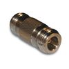
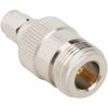
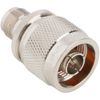
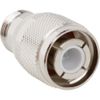
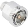
N-Type Adapter Specifications
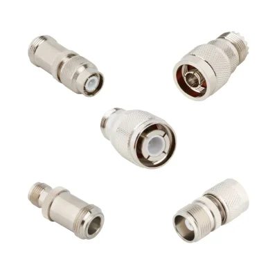
iPrece’s N-type adapter range includes 50 Ω and 75 Ω models, N-to-N adapters, and transitions to other RF connector families. The tables below summarize available configurations and indicative performance. Exact ratings depend on the selected adapter and operating frequency.
RF and Electrical Specifications
Parameter | Available Options / Indicative Values |
Nominal impedance | 50 Ω; selected 75 Ω models |
Frequency range | DC–11 GHz common; selected models to 18 GHz |
Higher-frequency 75 Ω options | Selected HD-BNC transitions to 12 GHz |
VSWR, indicative | Approximately 1.10:1–1.50:1 |
Insertion loss, indicative | Approximately 0.05–0.30 dB for matched two-port adapters |
Low-PIM options | Available on selected 50 Ω models |
RF power handling | Depends on frequency and both connector interfaces |
VSWR and insertion-loss figures are industry reference ranges. Confirm performance over the required frequency band for the exact adapter.
Connector Interfaces and Mechanical Configurations
Parameter | Available Options |
Adapter types | In-series; between-series |
N-to-N genders | Male–male; male–female; female–female |
Common transitions | SMA, TNC, BNC, HD-BNC, MCX, MMCX, SMB |
Telecom transitions | 7/16 DIN, 4.3-10, 4.1/9.5, 2.2-5, NEX10 |
Other transitions | F-type, UHF, FME, QMA, SMP, PSMP |
Reverse-polarity options | RP-N, RP-SMA, RP-TNC, RP-BNC |
Body configurations | Straight; right-angle; tee |
Mounting options | Inline; bulkhead; four-hole flange |
N-type coupling | 5/8-24 threaded |
Mating durability, indicative | Approximately 500 cycles |
Materials and Finishes
Component | Available Materials / Finishes |
Body material | Primarily brass; selected stainless-steel models |
Contact material | Beryllium copper, phosphor bronze, brass |
Insulator material | Primarily PTFE; selected acetal or styrene-based insulators |
Body finish | Nickel, white bronze, silver, gold |
Stainless-steel finish | Passivated |
Contact finish | Gold, silver; selected tin finishes |
Environmental Ratings and Qualification Options
Parameter | Available Options |
Standard temperature range | −40 °C to +85 °C on selected models |
Extended temperature ranges | −55 °C to +155 °C; −65 °C to +165 °C |
Ingress protection | IP67 or IP68 on selected models |
Military-qualified option | M55339/20-00201 adapter listed in the range |
How to Select the Right N-Type Adapter
Start by identifying the two interfaces that need to connect. An in-series N-Type adapter connects interfaces within the N-Type connector family, while a between-series adapter transitions between N-Type and another coaxial interface. The appropriate configuration depends on the connected equipment, signal requirements, and available installation space.
Before selecting an N-Type RF adapter, verify:
Connector gender: Identify whether each side requires an N-Type plug or jack.
Interface combination: Confirm whether both ends are N-Type or whether a transition to another connector family is required.
Impedance: N-Type interfaces are commonly used in 50 Ω systems. Specify 75 Ω only when the complete connection is designed for that impedance and a suitable configuration is available.
Frequency range: Check the rated range of the exact adapter and both mating interfaces.
RF performance: Evaluate insertion loss, VSWR or return loss, and power limits where specified.
Body geometry: Choose straight or right-angle orientation according to connector access, panel clearance, and cable routing.
Mounting requirements: Determine whether a free-standing, panel-mounted, or bulkhead arrangement is required.
An adapter that fits mechanically may still be unsuitable for the operating frequency or impedance. Verify the electrical ratings of the complete connection before installation.
N-Type Adapter Applications
N-type adapters provide reliable RF interface transitions across test, communications, antenna, broadcast, and OEM applications.
RF Test and Measurement
N-type adapters connect signal generators, network analyzers, power meters, and devices under test. They bridge different connector interfaces and serve as replaceable connections that reduce wear on instrument ports.
Wireless Infrastructure and Distributed Antenna Systems
In base stations and distributed antenna systems, adapters connect radio equipment, feeder cables, and distribution hardware. Between-series configurations bridge N-type interfaces to connections such as 7/16 DIN, SMA, and 4.3-10.
Antenna Feeds and Enclosure Connections
At antenna feed points and enclosure boundaries, adapters connect external coaxial cables to internal RF paths. Bulkhead versions provide fixed feedthrough connections on outdoor radio housings and equipment panels.
Radar and Defense Communications
N-type RF adapters connect antenna feeds, receiver inputs, and test equipment in radar and defense communications systems. They also provide interface transitions during subsystem integration, maintenance, and RF performance testing.
Broadcast and Video Systems
75 Ω N-type adapters connect compatible coaxial video equipment, patch panels, and test instruments. N-to-BNC and N-to-HD-BNC transitions link different connector interfaces within broadcast installations and video measurement systems.
OEM Equipment and Production Fixtures
N-type adapters provide fixed RF interfaces on OEM enclosures, test racks, and production fixtures. Panel-mounted versions bring internal RF connections to accessible ports for assembly testing, servicing, and repeated device connections.
Technical Specifications and Ordering Requirements
Before requesting a quote, define the interface and operating requirements of the application.
Connector combination: Specify N-Type to N-Type or the required between-series transition.
Connector gender: Identify plug or jack at each end.
Body and mounting: State whether a straight, right-angle, panel-mount, or bulkhead configuration is needed.
Impedance and frequency: Provide the system impedance and complete operating frequency range.
RF performance: Specify any required insertion-loss, VSWR, or return-loss limits.
Power and environment: State the operating power and any relevant temperature, moisture, vibration, or outdoor installation requirements.
Quantity and documentation: Provide the quantity and any project-specific inspection or documentation requirements.
When specifying an N-Type adapter connector, describe both ends of the connection rather than providing only the connector family name. This helps clarify gender, interface series, mounting, and electrical requirements.
N-Type adapter pricing depends on the interface combination, gender, body geometry, frequency rating, RF performance, and mounting requirements. For a meaningful comparison, evaluate options against the same technical requirements rather than comparing price alone.
Quality and Standards
Buy N-type adapters from iPrece with direct engineering support, controlled quality processes, and documentation aligned with your project’s requirements.
ISO 9001:2015 quality management: Our certified quality system supports controlled production, consistent inspection, and handling of nonconforming products.
Pre-shipment validation: Mechanical and electrical checks assess conformity to specified requirements. Calibrated VNA testing verifies RF performance, including VSWR and insertion loss.
Compliance support: We help confirm the applicable RoHS, REACH, and qualification documentation for your selected adapter, keeping procurement approvals tied to the actual supplied product.
Direct engineering access: Our RF team helps resolve compatibility questions and clarify acceptance limits and required test evidence before you commit to an order.