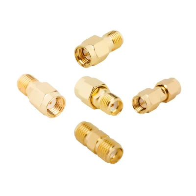

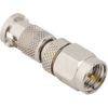
SMA Adapter Specifications
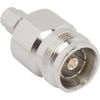
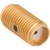
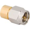
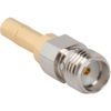
iPrece’s SMA adapter range includes 50 Ω in-series and between-series configurations, with straight, right-angle, tee, and panel-mount options. Frequency ratings, materials, and environmental protection depend on the selected model.
Electrical Performance
Specification | Available Ratings / Options |
Nominal impedance | 50 Ω |
Standard SMA-to-SMA frequency ratings | 12.4 or 18 GHz |
Selected high-performance SMA-to-SMA models | Up to 22 GHz |
Maximum VSWR | 1.20:1 on selected 26.5 GHz SMA-to-2.92 mm models |
Insertion loss | Confirm for the selected part and frequency |
Low-PIM options | Selected 4.3-10, 7/16 DIN, and NEX10 transitions |
VSWR and insertion-loss limits apply to the complete adapter configuration. Low-PIM performance requires a specified test frequency, power level, and acceptance limit.
Adapter Interfaces and Frequency Ratings
Adapter Interface | Listed Maximum Frequencies |
SMA to SMA | 12.4, 18, or 22 GHz |
SMA tee adapters | 12.4 GHz |
SMA to RP-SMA | 18 GHz |
SMA to 2.92 mm | 26.5 GHz; selected 40 GHz listings* |
SMA to SMP | 15, 18, or 26.5 GHz |
SMA to TNC / RP-TNC / RP-N | 11 GHz |
SMA to QMA | 6 or 18 GHz |
SMA to SMC | 10 or 18 GHz |
SMA to PSMP | 10 GHz |
SMA to SSMA | 12.4 GHz |
SMA to BNC / RP-SMB / SSMB / FAKRA | 4 GHz |
SMA to MCX / MMCX / RP-MMCX / HD-BNC | 6 GHz |
SMA to AMC / AMC4 / U.FL / HD-EFI | 6 GHz |
SMA to AFI | 3 or 6 GHz |
SMA to AMMC | 18 GHz |
SMA to 4.3-10 / 7/16 DIN / NEX10 | 6 GHz |
SMA to FME | 1 GHz |
SMA to UHF | 300 MHz or 2.5 GHz |
SMA to Mini-UHF | 2.5 GHz |
SMA RF switch test probes | 6 GHz |
* For 40 GHz SMA-to-2.92 mm listings, confirm the complete adapter and mating-interface ratings before ordering. Mechanical compatibility alone does not establish frequency performance.
Gender, Orientation, and Mounting
Specification | Available Options |
Adapter format | In-series; between-series |
Two-port gender combinations | Male–male; female–female; male–female |
Body orientation | Straight; 90° right angle; tee |
Reverse-polarity interfaces | RP-SMA, RP-TNC, RP-N, RP-MMCX, RP-SMB |
Panel mounting | Bulkhead; 4-hole flange |
Quick-connect options | Selected SMA quick-connect designs |
Minimum mating life | 500 cycles on selected SMA-to-2.92 mm models |
Materials and Finishes
Component | Available Materials / Finishes |
Body material | Brass; stainless steel; selected beryllium-copper constructions |
Body finish | Gold, nickel, white bronze, passivated stainless steel; selected black finishes |
Contact material | Beryllium copper, brass, phosphor bronze |
Contact finish | Gold; silver on selected models |
Insulator material | PTFE; selected PEEK or Ultem 1000/PTFE constructions |
PFAS-free options | Selected PEEK-insulated SMA-to-SMA models |
Operating Temperature and Environmental Protection
Specification | Available Ratings / Options |
Common operating-temperature grade | −65 °C to +165 °C |
Additional temperature grades | −40 °C to +85 °C; −40 °C to +125 °C |
Other selected temperature grades | −55 °C to +125 °C or +155 °C |
Ingress protection | IP67 or IP68 on selected models |
How to Select the Right SMA Adapter
Start with the interfaces you need to connect. An in-series SMA adapter connects interfaces within the same connector family, while a between-series SMA adapter connects SMA equipment to a different RF connector family. The right configuration depends on connector gender, available installation space, and the electrical requirements of the complete connection.
Before selecting an SMA RF adapter, verify:
Connector gender: Confirm whether each side requires a plug (male) or jack (female), including the center contact and coupling interface.
Interface combination: Determine whether both ends use SMA or whether a transition to another coaxial interface is required.
Orientation and mounting: Choose a straight or right-angle body according to cable routing, clearance, and access.
Impedance: SMA interfaces are commonly used in 50 Ω RF systems. Verify the impedance of the adapter and connected components.
Frequency rating: Confirm that the adapter supports the entire operating band, not only the nominal or center frequency.
RF performance: Check insertion loss, VSWR or return loss, and other specified limits where relevant.
Mechanical compatibility: Verify thread engagement, mating geometry, connector condition, and any installation torque requirements.
A connector that physically mates with an SMA interface is not automatically suitable for every frequency or measurement application. Verify the rated performance of the complete connection before installation.
SMA Adapter Types and Configurations
SMA adapters are available in different interface combinations, gender arrangements, and body geometries. These choices determine how equipment connects and how the adapter fits into the assembly.
In-Series SMA Adapters
An in-series SMA adapter connects two interfaces within the same connector family. It is commonly used to provide the required gender arrangement or connection geometry while keeping the connector series unchanged.
Depending on the configuration, an in-series adapter may have plug-to-plug, jack-to-jack, or plug-to-jack interfaces. Straight and right-angle bodies accommodate different installation constraints. Before selecting an adapter, confirm the required end arrangement and check that both mating interfaces are compatible.
Between-Series SMA Adapters
A between-series adapter connects an SMA interface to another coaxial connector family. For example, an SMA-to-2.92 mm adapter can provide a transition between equipment using those two interfaces, subject to the connector ratings and mating requirements.
When choosing an SMA-to-RF adapter or an SMA-to-coax adapter, identify the specific connector family on the other side. “RF” or “coax” alone does not define the mating interface, impedance, or frequency capability.
Straight and Right-Angle SMA Adapters
A straight adapter is suitable when the connected ports align directly and there is enough clearance for the adapter and coupling nuts. A right-angle SMA coaxial adapter can help route a connection around a space constraint or reduce the clearance needed behind a panel.
The orientation must suit both the mating ports and the cable path. Avoid forcing a cable into a tight bend immediately beside the adapter, as this can place mechanical stress on the connector and affect the connection.
SMA Adapter and Cable Configurations
A rigid SMA adapter provides a short transition between connector interfaces. An SMA adapter cable or SMA cable adapter assembly may be more appropriate when the connected equipment is separated by a distance or requires flexible routing.
Use a rigid adapter for a direct connection where clearance permits. When cable length, bend radius, movement, or routing is part of the design, evaluate a suitable cable assembly instead. Do not treat an adapter and a cable assembly as interchangeable components.
SMA Adapter Electrical Compatibility
An SMA adapter must match the electrical requirements of the connected RF system. Connector appearance alone is insufficient to establish compatibility.
Selection parameter | What to check | Why it matters |
Impedance | Adapter and connected-system impedance | Impedance mismatch can increase reflections and measurement error |
Frequency range | Rated operating band of the exact adapter | The full signal band must remain within the specified limits |
Insertion loss | Loss through the adapter at relevant frequencies | Additional loss changes the signal level delivered to the next component |
VSWR / return loss | Specified matching performance | Poor matching can degrade system performance |
Connector interface | SMA, 2.92 mm, or another defined coaxial interface | Similar-looking interfaces are not all interchangeable |
Gender and center contact | Plug or jack at each end | Correct mating geometry is essential for a secure connection |
Power and voltage limits | Applicable model ratings | Limits depend on the design and operating conditions |
Impedance and Signal Integrity
SMA interfaces are commonly used in 50 Ω RF systems, but impedance must still be checked for the selected adapter and connected equipment. A connector that appears mechanically compatible may introduce an impedance discontinuity if the electrical interfaces are not properly matched.
For test and measurement applications, review the adapter's VSWR or return loss over the required frequency band. Also consider the combined effect of the adapter, cable, connectors, and device ports rather than evaluating the adapter in isolation.
Frequency Rating and RF Performance
The maximum frequency of an SMA adapter depends on its design, interface combination, and documented performance. Do not assume all SMA adapters support the same operating frequency.
For high-frequency RF or microwave connections, verify the specified frequency range and matching performance of the complete mating arrangement. If the adapter joins two different connector families, the usable performance may be limited by the lowest-rated component or interface in the connection.
SMA Adapter Applications
The appropriate SMA adapter depends on the signal path, equipment interfaces, and installation constraints.
RF Test and Measurement
SMA adapters connect compatible instrument ports, test cables, fixtures, and devices under test. For calibrated measurements, connector condition, correct mating, impedance, and frequency rating are especially important because adapter-related mismatch can affect measurement results.
Antenna and Wireless Equipment
An SMA RF adapter can connect equipment with compatible SMA interfaces or provide a transition to another specified coaxial interface.
RF Modules and Compact Assemblies
Straight and right-angle adapters help accommodate different mechanical layouts in RF modules and compact equipment.
Cable and Equipment Interconnection
An SMA cable adapter or a suitable SMA adapter cable assembly can help connect equipment when routing or separation distance makes a direct rigid adapter impractical.
Technical Specifications and Ordering Requirements
Before requesting a quote, define the interface and performance requirements of your application.
Connector combination: Specify an in-series SMA adapter or the required between-series transition.
Gender: Identify the required plug and jack arrangement at each end.
Body geometry: State whether a straight or right-angle configuration is required.
Impedance and frequency: Provide the system impedance and complete operating frequency range.
RF performance: Specify any insertion-loss, VSWR, or return-loss limits required by the application.
Installation constraints: Include panel thickness, mounting needs, clearance, and cable-routing requirements where relevant.
Quantity and documentation: Provide the required quantity and any project-specific inspection or documentation requirements.
Quality & Standards
iPrece supports SMA RF adapter sourcing with controlled manufacturing, mechanical and electrical validation, and lot traceability. Model-specific specifications and agreed inspection requirements support design approval and repeat procurement.
ISO 9001:2015 quality management: Certified quality processes support controlled manufacturing, inspection, and consistent handling of product requirements.
Mechanical validation: Pre-shipment checks assess adapter construction and mechanical conformity against applicable product specifications.
RF verification: Calibrated VNA testing supports VSWR and insertion-loss verification. Required frequency coverage, acceptance limits, and supplied reports are confirmed with the quotation.
Material compliance: RoHS and REACH documentation requirements can be included in your inquiry, with applicable declarations confirmed for the selected SMA coaxial adapter.
Model-specific qualification: Sealing, vibration, and military qualification claims apply to the models with supporting documentation and defined test conditions.
Include any required qualification standard, environmental test profile, or measured RF test report in your RFQ for confirmation before ordering.