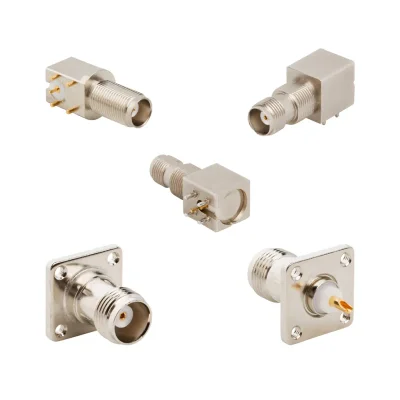

TNC Adapter Specifications
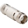
iPrece TNC adapters are available in 50 Ω and 75 Ω configurations, with straight, right-angle, and tee designs. Most listed models support frequencies up to 11 GHz, while selected 50 Ω adapters are rated up to 18 GHz. The following specifications summarize the available product range; individual ratings depend on the adapter configuration.
RF and Electrical Specifications
Specification | Available Ratings / Options |
Nominal Impedance | 50 Ω, 75 Ω |
Maximum Frequency | 11 GHz common; selected models up to 18 GHz |
Frequency Ratings Across Models | 0.2–18 GHz maximum rated frequency |
VSWR (Max) | Model-specific; contact engineering |
Insertion Loss | Model-specific; contact engineering |
RF Power Handling | Model-specific; not listed |
Connector Interfaces and Frequency Ratings
Adapter Interface | Listed Maximum Frequencies |
TNC to TNC (50 Ω) | 11–18 GHz |
TNC to TNC (75 Ω) | 1–11 GHz |
TNC to RP-TNC | 4–11 GHz |
TNC to AMC | 3–6 GHz |
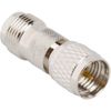
TNC to Mini-UHF / UHF | 2.5 GHz |
TNC to FME | 0.2–1 GHz |
TNC to QMA | 18 GHz |
Mechanical Configurations and Mounting
Specification | Available Options |
Adapter Type | In-Series, Between-Series |
Gender Configurations | Jack–Jack, Jack–Plug, Plug–Plug |
Body Orientation | Straight, Right Angle, Tee |
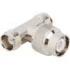
Tee Configurations | Jack–Jack–Jack, Jack–Plug–Jack |
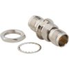
Panel Mounting | Bulkhead, 2-Hole Flange, 4-Hole Flange |
Isolated Mounting | Selected bulkhead models |
Coupling Interface | Threaded TNC |
Materials and Finishes
Component | Available Materials / Finishes |
Body Material | Brass; selected zinc diecast |
Body Finish | Nickel, White Bronze, Tin/Nickel |
Center Contact Material | Phosphor Bronze, Beryllium Copper, Brass |
Contact Plating | Gold, Silver |
Insulator Material | PTFE, Delrin, PPO, Polypropylene |
Environmental and Operating Conditions
Specification | Available Ratings / Options |
Standard Operating Temperature | −40 °C to +85 °C |
Extended Operating Temperature | −65 °C to +165 °C (selected models) |
Environmental Protection | IP67 (selected bulkhead models) |
Electrical Isolation | Selected insulated bulkhead configurations |
Confirm model-specific frequency, VSWR, insertion loss, temperature, and environmental ratings before final selection.
How to Select the Right TNC Adapter
Selecting a TNC adapter requires more than matching the connector family. The mating interfaces, impedance, operating frequency, RF performance and mechanical requirements must all be compatible with the intended signal path.
Connector interface and gender: Specify the connector series and gender at both ends. Confirm that each plug or jack mates with the intended counterpart and that the adapter does not introduce an incompatible interface.
Standard or reverse polarity: Check whether the connection requires standard TNC or reverse-polarity TNC (RP-TNC). These interfaces have different center-contact arrangements and should not be treated as interchangeable.
System impedance: Match the adapter to the system’s nominal impedance. TNC interfaces are available in 50 Ω and selected 75 Ω configurations, but the required impedance must be explicitly supported by the chosen adapter.
Frequency range: Verify the adapter’s specified operating band across the entire application range, including the upper frequency limit. A connector-family rating does not automatically establish the performance of the complete adapter.
RF matching and loss: Review VSWR or return loss, insertion loss and, where required, the relevant S-parameter data. These values should cover the frequencies at which the system will operate.
Mechanical configuration: Consider connector orientation, clearance, mounting requirements, access for tightening and the expected mechanical loading.
Applications for TNC RF Adapters
Adding an adapter introduces another interface into the signal path. Where the application has tight loss, matching or repeatability requirements, evaluate the adapter and the complete connected path rather than relying on connector-family characteristics.
TNC adapters are used to connect, extend, and reconfigure coaxial RF connections across communication systems, test equipment, industrial installations, and aerospace electronics.
RF Test and Measurement
TNC adapters connect test cables, RF instruments, and devices under test in laboratory setups. They also provide replaceable interface connections for equipment ports exposed to frequent mating cycles.
Telecommunications and Base Stations
In wireless infrastructure, TNC coax adapters connect RF cable assemblies, radio modules, and antenna feed lines. They also accommodate interface transitions during base-station upgrades and equipment replacements.
Industrial Automation and Telemetry
TNC adapters connect industrial wireless modules, telemetry equipment, and coaxial antenna cables in automated machinery and remote monitoring installations, where secure threaded RF connections are commonly used.
Aerospace and Defense Systems
TNC RF adapters interconnect RF modules, coaxial harnesses, and communication equipment in avionics, radar subsystems, and vehicle-mounted electronics, accommodating connector transitions and mechanical routing requirements.
Panel and Enclosure Feedthroughs
Bulkhead and flange-mount TNC adapters provide coaxial connections through equipment panels, instrumentation enclosures, and RF cabinets, linking internal signal paths to external cables, antennas, or test equipment.
Antenna and Radio Equipment Integration
Between-series TNC adapters connect existing antenna cables and radio equipment using different RF interfaces, including RP-TNC, FME, and UHF, supporting equipment retrofits and wireless system integration.
RF Prototyping and Test Fixtures
TNC adapters support temporary cable extensions, connector transitions, and right-angle connections during RF prototype development. Tee configurations provide three-port junctions for experimental setups without matched power division.
Information to Include When Requesting a TNC Adapter
To identify a suitable configuration and obtain a meaningful quotation, provide:
The connector family and gender required at each end.
Whether the interface must use standard TNC or RP-TNC polarity.
The required system impedance: 50 Ω or 75 Ω.
The operating frequency range and acceptable VSWR, return loss or insertion loss.
Any power-handling or voltage requirements.
The required geometry and mounting arrangement, including clearance constraints.
The operating environment, quantity and any required inspection or test documentation.
These details help distinguish a mechanically compatible adapter from one that meets the electrical and environmental requirements of the application.
Quality & Standards
iPrece TNC adapters are manufactured with attention to interface precision, consistent RF performance, and reliable mechanical connections. Our quality control procedures support dependable integration into RF systems, from laboratory instrumentation to industrial and telecommunications equipment.
Mechanical Quality Control: Inspection of connector fit, contact engagement, threaded coupling, and mechanical integrity to support reliable mating.
RF Performance Verification: Electrical checks covering VSWR, return loss, and insertion loss, with performance requirements evaluated for the specified adapter.
Interface Standards: IEC 61169-17 and MIL-STD-348 provide relevant TNC interface requirements. Compliance is confirmed for applicable configurations rather than assumed across the entire range.
Quality Management & Traceability: ISO 9001:2015-certified manufacturing operations support consistent quality and procurement documentation.
Additional Qualification: Application-specific environmental evaluation and enhanced RF testing, including intermodulation assessment, can be discussed for demanding projects.