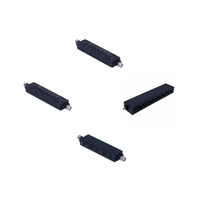

RF Bandpass Filter Applications
RF coaxial bandpass filters are critical components in modern frequency-selective systems. They allow specific frequency ranges to pass seamlessly while severely attenuating unwanted signals and out-of-band interference. Their reliability directly impacts signal integrity, interference management, and receiver sensitivity across multiple demanding industries.
Wireless Communication Infrastructure: Base stations, repeaters, and distributed antenna systems (DAS) rely on bandpass filters to isolate assigned frequency bands and eliminate adjacent-channel interference, ensuring flawless signal transmission.
Military & Commercial Radar: Precision is paramount in radar systems. RF bandpass filters select the exact radar frequency while attenuating noise, preserving weak return signals on the receiver side, and handling high power on the transmit side.
Satellite Communication (SATCOM): In SATCOM transceivers and ground stations, bandpass filters isolate designated uplink and downlink bands, suppressing cross-channel interference and securing clear communication links.
RF Receivers & Front-End Filtering: Placed at the receiver's front end, these filters block strong out-of-band signals before they reach sensitive stages, preventing receiver overload and maximizing the detection of weak signals.
Test and Measurement Equipment: High-precision test setups utilize bandpass filters to suppress harmonics and isolate specific frequencies, ensuring absolute accuracy in RF component characterization and signal generation.
RFID Systems: In inventory tracking and access control, an RFID bandpass filter isolates reader signals and tags in specific bands (like UHF), preventing out-of-band noise from corrupting data reads.
RF Bandpass Filter Types and Topologies
Our product line includes multiple filter topologies to meet different performance and integration requirements.
Filter Topology | Optimal Frequency Range | Key Strengths | Form Factor | Common Applications |
RF Cavity | Microwave / High Power | High selectivity, lowest insertion loss | Scales with frequency | Radar, SATCOM, Base Stations |
Lumped LC | Lower RF / HF (3–30 MHz) | Flexible circuit-level integration | Highly compact | Tactical radios, MRI, Portables |
Ceramic | UHF / Low Microwave | High Q-factor, excellent temperature stability | Ultra-compact (SMD) | GPS, Wi-Fi, Mobile handsets |
Suspended Substrate | High Frequency / Microwave | Low-loss, broadband performance | Compact integration | EW systems, Microwave receivers |
RF Cavity Bandpass Filters
RF cavity bandpass filters use resonant cavities to provide frequency-selective filtering. Depending on their design, they can offer high selectivity and low insertion loss for RF and microwave applications. These filters are frequently deployed in demanding microwave systems. Physical dimensions and power-handling capabilities vary depending on the specific design and frequency requirements.
Common Applications & Industries: Wireless communication infrastructure (base stations and cell towers), military and commercial radar systems, satellite communications (SATCOM), aerospace, and high-power broadcast transmitters.
Lumped LC Bandpass Filters
Lumped LC filters use discrete inductors and capacitors to create frequency-selective networks. Offering a compact footprint for space-constrained circuit-level applications, these components are widely used in lower-frequency RF systems. This includes demanding HF bandpass filter requirements (such as 3–30 MHz), although their practical operating range depends on component characteristics and circuit design.
Common Applications & Industries: Portable wireless devices, military tactical radios (manpacks), intermediate frequency (IF) filtering stages, consumer electronics, medical imaging equipment (such as MRI), and portable test equipment.
Suspended Substrate Bandpass Filters
Suspended substrate filters use a suspended dielectric structure to implement microwave filtering networks. Depending on the design, this topology can support low-loss performance and compact integration in high-frequency applications.
Common Applications & Industries: Electronic warfare (EW) systems, broadband microwave receivers, radar warning receivers, microwave point-to-point backhaul links, and precision aerospace instrumentation.
Ceramic RF Bandpass Filters
A ceramic RF bandpass filter utilizes high-dielectric ceramic resonators to achieve excellent frequency selectivity in an ultra-compact, surface-mount (SMD) or coaxial package. These filters are highly valued for their high Q-factor and superior temperature stability compared to standard LC designs.
Common Applications & Industries: GPS and GNSS receivers, Wi-Fi routers, mobile telecommunications (4G/5G handsets), and specialized IoT transceivers.
RF Bandpass Filter Specifications and Characteristics
Evaluating the correct filter parameters is essential for successful system integration. Our standard RF band pass filters feature a nominal 50 Ω impedance. Key specifications to consider include:
Center Frequency: The nominal frequency at the middle of the filter's passband, defined according to the filter design and specification convention.
Passband Frequency Range: The lower and upper frequency limits over which the filter is designed to pass signals.
Bandwidth: The frequency span between the lower and upper passband edges. Depending on your application, we offer both RF narrow bandpass filter designs for high-selectivity signal isolation and wide band pass filter solutions for broadband data transmission.
Insertion Loss: The signal power loss introduced by the filter within its passband.
Out-of-Band Rejection: The attenuation provided by the filter at frequencies outside its specified passband.
Return Loss and VSWR: Parameters used to evaluate impedance matching at the filter ports.
Power Handling: The maximum applicable RF power, distinguishing between continuous-wave (CW) and peak power ratings where specified.
Connector Interface: Available options include SMA, 2.92 mm, TNC, and N-Type interfaces, depending on the product model.
Operating Temperature: The specified temperature range within which the filter is designed to operate.
Note: Passive RF bandpass filters attenuate signals outside their passband and do not provide amplification. Quality factor (Q) and filter order are important design parameters that influence bandwidth, selectivity, and the overall frequency response.
Visual Recommendation: Include a frequency-response graph showing the filter's response versus frequency. Label the passband, center frequency, lower and upper passband edges, and stopbands. The vertical axis can represent insertion loss or transmission response (S21 in dB), provided the chosen convention is clearly identified.
How to Choose the Right Bandpass RF Filter
Selecting an RF bandpass filter requires analyzing the complete system requirements. Consider the following factors when specifying the appropriate component.
1. Determine the Required Center Frequency and Passband Range
Start by identifying the target operating frequency and the frequency range that the filter must pass. The center frequency should align with the system's intended operating band, while the passband limits must accommodate the full range of required signals. Make sure the selected RF BPF filter covers the necessary frequencies without unnecessarily passing unwanted signals.
2. Establish the Required Bandwidth
Determine the bandwidth needed to accommodate the intended signal, including its modulation and occupied spectrum. A filter with insufficient bandwidth may attenuate portions of the desired signal and cause distortion, while an excessively wide passband may allow additional unwanted signals to reach the system. Consider the required bandwidth and the filter's passband shape together.
3. Define the Maximum Acceptable Insertion Loss
Insertion loss determines how much signal power is lost as the signal passes through the filter. Excessive insertion loss can reduce transmitted signal power or weaken signals entering a receiver, potentially affecting overall system performance. Compare the filter's specified insertion loss with the available link budget and the sensitivity requirements of the application.
4. Specify the Required Out-of-Band Rejection
Evaluate which unwanted frequencies or interfering signals must be attenuated and determine the required rejection levels at those frequencies. An RF bandpass filter with insufficient rejection may allow adjacent-channel signals, harmonics, or other interference to pass into the system. Check the rejection specifications at the actual frequencies of concern rather than relying only on a general rejection rating.
5. Verify CW and Peak RF Power-Handling Requirements
Check the maximum RF power the filter must withstand under normal and peak operating conditions. Continuous-wave (CW) power handling indicates the supported continuous input power, while peak power handling addresses short-duration power levels. Consider the signal waveform, duty cycle, temperature, and operating conditions when comparing power ratings to avoid overheating, excessive stress, or component damage.
6. Confirm System Impedance and Connector Compatibility
Ensure that the filter's nominal impedance matches the rest of the RF system. Many RF and microwave systems use 50 Ω impedance, but this should always be verified against the equipment specifications. Also check connector type, gender, and interface compatibility, such as SMA, 2.92 mm, TNC, or N-Type, to avoid mismatches and unnecessary adapters.
7. Review Operating Temperature and Environmental Requirements
Verify that the filter's specified operating temperature range covers the expected conditions in the installation environment. Temperature variations can affect electrical characteristics such as center frequency, insertion loss, and return loss. For outdoor, industrial, or other demanding applications, also consider relevant environmental requirements such as humidity, vibration, and exposure conditions.
8. Evaluate Mechanical Dimensions and System Integration
Finally, check the filter's physical dimensions, weight, mounting configuration, and available installation space. Consider how the component will connect to adjacent RF equipment and whether its mechanical design is compatible with the system enclosure and cable routing. For custom installations, discuss dimensional and mounting requirements with the manufacturer before finalizing the filter selection.
The right filter should meet the complete electrical, mechanical, and environmental requirements of the intended application rather than being selected based on frequency range alone.
Quality Assurance and RF Filter Testing
Operating under an ISO 9001 certified quality management system, iPrece emphasizes strict quality control and performance verification throughout its bandpass RF filter design and manufacturing processes. We rigorously evaluate electrical performance using Vector Network Analyzers (VNAs) to verify key parameters such as:
Passband insertion loss
Return loss and VSWR
Frequency response
Out-of-band rejection
We can perform any additional electrical, environmental, or mechanical testing your project requires. Simply specify your necessary testing standards, and we will conduct the evaluations and provide comprehensive test reports, including VNA measurement plots, directly to you.
Custom RF Bandpass Filter
If off-the-shelf standard products don't meet your project's unique demands, our engineering team provides end-to-end custom RF design and manufacturing services. Whether you need a fixed-frequency solution or a tunable RF bandpass filter, we can tailor:
Center frequencies and ultra-specific bandwidths
Adjustable RF bandpass filter designs for dynamic frequency selection
Programmable and digitally tunable RF bandpass filter solutions for advanced transceivers
Variable RF bandpass filter configurations for adaptive interference mitigation
Custom footprints, mounting configurations, and high-power handling upgrades
Seamless Supply: From Quote to Global Delivery
iPrece follows a structured process to review filter requirements, confirm precise specifications, and coordinate secure order fulfillment.
Requirement: Specification Submission or Custom Design Request
Engineering Review: Technical Feasibility and Configuration Verification
Proforma Invoice: Formal Pricing and Lead Time Issuance
Payment: Order Confirmation and Payment Processing
Production & Testing: Manufacturing and VNA Verification to Approved Specifications
Global Delivery: Final Quality Inspection, Secure Packaging, and Worldwide Shipment
This structured manufacturing and fulfillment approach ensures that every RF filter meets the stringent electrical and mechanical requirements of its intended system. Maintaining consistency from the initial engineering review to the final shipment is essential for reliable RF bandpass filter performance in complex frequency-selective networks.