TNC to TNC Cable
Secure extensions for antennas, radios, and vibration-prone RF equipment.
Configure →Build custom TNC cable assemblies that remain securely connected through vibration, movement, and environmental exposure. Use our custom RF cable assembly tool to define your interfaces, coaxial cable, length, orientation, and performance requirements.
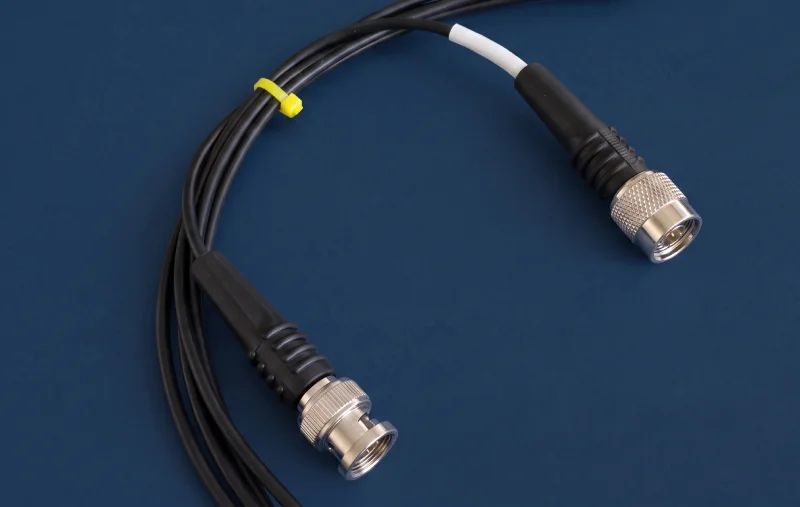
Submit your custom RF requirements for a verified technical review and formal wholesale pricing within 24 hours.
Configure each assembly with the required gender, orientation, bulkhead mounting, cable family, and finished length.
Secure extensions for antennas, radios, and vibration-prone RF equipment.
Configure →Connect rugged TNC ports to compact RF modules and instruments.
Configure →Build low-loss antenna connections for outdoor and mobile RF systems.
Configure →Bridge threaded installations with BNC test or legacy equipment.
Configure →Connect TNC and F-type interfaces in wireless antenna systems.
Configure →Route external TNC connections to compact embedded RF hardware.
Configure →Use this overview to narrow the build, then select a cable family that fits your system.
| Cable | Best for | Flexibility | Loss | Impedance |
|---|---|---|---|---|
| Flexible RF coax | General RF and antenna runs | High | Moderate | 50 / 75 Ω |
| Low-loss flexible | Longer outdoor RF runs | Medium–high | Low | 50 Ω |
| Broadcast coax | Video and broadband systems | High | Low–moderate | 75 Ω |
| Semi-rigid | Precision fixed routing | Low | Low | 50 Ω |
| Hand-formable | Compact controlled routing | Medium | Low | 50 Ω |
Final compatibility and performance are confirmed during engineering review.
The threaded TNC interface maintains its mechanical grip while the cable, shielding, and protective construction can be engineered around the actual RF path.
The threaded coupling resists accidental disconnection under vibration, shock, movement, and repeated mechanical stress.
Standard assemblies operate up to 11 GHz, while qualified combinations support up to 18 GHz.
Eligible assemblies can incorporate IP67 sealing, strain relief, and armor for demanding installations.
Choose standard or reverse polarity, 50 Ω or 75 Ω impedance, and straight, right-angle, or bulkhead connectors to fit the equipment directly.
TNC cable assemblies are built for systems where accidental decoupling, mechanical movement, or environmental exposure could compromise the RF connection.
Secure signal routing for equipment exposed to shock and vibration.
Outdoor antenna feeds for base stations, GPS/GNSS, RFID, and distributed wireless systems.
Reliable RF connections for heavy machinery and equipment in continuous motion.
Instrument connections for extended tests and setups where cables must remain securely mated.
A TNC cable assembly is a complete coaxial interconnect terminated with at least one threaded TNC connector. Unlike BNC’s bayonet coupling, the TNC interface stays securely mated under vibration and movement.
The following values represent capabilities available across the product family; final ratings are confirmed for the selected connectors, cable, length, and construction.
Parameter | Available Specification |
Impedance | 50 Ω / 75 Ω |
Frequency range | DC–11 GHz standard; DC–18 GHz extended |
VSWR | 1.30:1 max through 11 GHz with qualified configurations |
Insertion loss | Specified for the finished length and operating frequency |
RF leakage | Up to -60 dB at 3 GHz with qualified interfaces |
Voltage rating | Up to 500 V peak |
Dielectric withstand | Up to 1500 VRMS with qualified components |
Insulation resistance | 5000 MΩ minimum with qualified components |
Power handling | Up to 316 W at 1 GHz and 25°C; configuration-dependent |
Parameter | Available Options |
Coupling mechanism | 7/16"-28 threaded |
Connector configurations | TNC to TNC and between-series assemblies |
Polarity | Standard / reverse polarity |
Gender | Plug / jack |
Orientation | Straight / right-angle |
Mounting | Free-hanging / bulkhead / panel mount |
Mating durability | 500 cycles minimum with qualified connectors |
Cable construction | Flexible, low-loss flexible, broadcast, semi-rigid, and hand-formable |
Finished length | Custom to drawing or BOM |
Bend radius | Determined by the selected cable |
Protective options | Strain relief, heat-shrink boots, weather-resistant jackets, and armor |
Parameter | Available Qualification |
Operating temperature | -65°C to +165°C with qualified components |
Environmental sealing | IP67 options available |
Thermal shock | MIL-STD-202, Method 107, Condition B |
Corrosion resistance | MIL-STD-202, Method 101, Condition B |
Vibration | MIL-STD-202, Method 204, Condition B |
Mechanical shock | MIL-STD-202, Method 213, Condition G |
Moisture resistance | MIL-STD-202, Method 106 |
Altitude | MIL-STD-202, Method 105, Condition C |
Interface standard | MIL-STD-348 |
Standard TNC and reverse-polarity TNC cable assemblies use the same threaded housing styles but opposite center-contact arrangements. Because polarity does not change the external plug or jack body, connectors that look mechanically compatible may still have the wrong internal contact.
Feature | Standard TNC | RP-TNC |
Plug center contact | Pin | Socket |
Jack center contact | Socket | Pin |
Threaded housing | Standard plug/jack arrangement | Same plug/jack arrangement |
Compatibility | Mates with standard TNC | Mates with RP-TNC |
Common applications | General RF, test, industrial, military | WLAN, RFID, antennas, wireless networking |
Each order is inspected against the approved drawing and specified acceptance requirements before release.
Continuity and Hi-Pot testing verify the integrity of the center conductor, dielectric, and shield.
VNA verification of insertion loss and VSWR is available at the specified operating frequencies, with test reports provided when required.
Dimensional and visual inspection confirms finished length, connector gender, polarity, orientation, and assembly workmanship.
Termination and retention checks verify crimp, solder, connector attachment, and strain relief, with lot traceability available for production orders.
Yes. We manufacture 50 Ω TNC assemblies for RF, wireless, antenna, industrial, and test systems, as well as 75 Ω configurations for compatible video and broadband equipment.
No. Although standard and reverse-polarity TNC connectors use similar threaded housings, their center contacts are reversed. Attempting to combine them results in two pins or two sockets facing each other.
Low-loss flexible coax is generally the best choice for longer TNC antenna runs because it reduces attenuation compared with standard flexible cable. The correct cable size depends on the run length, operating frequency, acceptable insertion loss, power level, routing space, and minimum bend-radius requirements.
Insertion loss increases as the cable becomes longer and typically rises further at higher frequencies. Total assembly loss also includes the TNC connectors and any right-angle or between-series transitions.
Yes. TNC cable assemblies can use straight or right-angle plugs and jacks, including front- and rear-mount bulkhead configurations. Right-angle connectors simplify routing in restricted spaces, while bulkhead connectors provide a fixed equipment-panel interface and can incorporate environmental sealing where required.
<p>Select your specifications online or upload complete drawings for engineering review.</p>