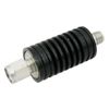
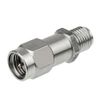
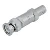
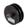
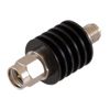
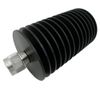
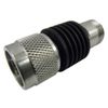
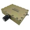
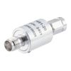
RF Attenuator Specifications
Compare fixed, manual step, programmable and continuously variable RF attenuators by frequency, attenuation, power and interface. These configurations cover different RF attenuation requirements, from fixed signal reduction to electronically controlled adjustment. The tables below show selected configurations; available combinations depend on the model.
Fixed Coaxial Attenuator Specifications
A fixed RF coaxial attenuator provides a defined attenuation value without requiring adjustment during operation. Choose a coaxial attenuator based on frequency, attenuation, power rating, impedance, and connector compatibility. Fixed values such as 3 dB, 6 dB, 10 dB, 20 dB, 30 dB, 40 dB, and 50 dB serve different signal-level requirements; the available value depends on the interface and model.
Interface | Maximum Frequency | Attenuation | Power Rating |
SMA | 18 GHz | 60 dB | 2 W |
BNC | 4 GHz | 3 dB | 10 W |
N-type | 18 GHz | 10 dB | 25 W |
N-type | 3 GHz | 30, 40 or 50 dB | 300 W |
2.92 mm | 40 GHz | 30 dB | 5 W |
2.4 mm | 50 GHz | 20 dB | 2 or 5 W |
1.0 mm | 110 GHz | 6, 10 or 20 dB | 0.5 W |
For a 3 dB RF attenuator, 10 dB RF attenuator, or 20 dB attenuator, verify the specified interface, frequency range, and power rating. A 40 GHz attenuator, for example, must support the full operating band at the required attenuation level. Do not assume that every fixed value is available with every connector or frequency rating.
Manual Step Attenuator Specifications
A manual step attenuator allows attenuation to be changed in defined increments. This makes it useful when test levels need repeatable adjustments without a continuously variable control. A switchable RF attenuator should be selected by its attenuation range, step size, frequency, impedance, and power rating.
Interface | Maximum Frequency | Attenuation Range | Step Size | Power Rating |
SMA, 50 Ω | 18 GHz | 0–99 dB | 1 dB | 2 W |
N-type, 50 Ω | 6 GHz | 0–70 dB | 1 dB | 2 W |
N-type, 50 Ω | 6 GHz | 0–60 dB | 10 dB | 2 W |
BNC, 75 Ω | 2.5 GHz | 0–91 dB | 1 dB | 2 W |
The required setting must fall within the model's attenuation range and available step size. For instance, a 1 dB, 2 dB, 7 dB, or 12 dB setting should be verified against the supported range and increments rather than assumed available in every manual step attenuator.
Programmable Attenuator Specifications
A programmable RF attenuator supports electronically controlled attenuation through an interface such as USB, TTL, or relay control. A digital RF attenuator or RF digital attenuator can be useful in automated test equipment and systems that require repeatable signal-level changes. Compare the control interface, attenuation range, step size, frequency, and permitted input power.
Control / RF Interface | Frequency | Attenuation Range | Step Size | Power Rating |
USB / 2.92 mm | 100 MHz–40 GHz | 0–30 dB | 1 dB | 0.2 W |
TTL / SMA | 30 MHz–6 GHz | 0–60 dB | 0.25 dB | 0.1 W |
TTL / SMA | 500 MHz–18 GHz | 0–60 dB | 0.06 dB | 1 W |
Relay / SMA | Up to 1 GHz | 0–31.5 dB | 0.5 dB | 1 W |
Relay / SMA | Up to 1.5 GHz | 0–127 dB | 1 dB | 1 W |
For automated applications, verify that the step resolution and control method meet the required adjustment accuracy and timing. A smaller step size does not automatically guarantee better attenuation accuracy.
Continuously Variable Attenuator Specifications
An adjustable RF attenuator provides continuous control of attenuation over a specified range. Mechanical and voltage-controlled designs suit different control requirements. A voltage controlled RF attenuator is adjusted through a control voltage, while a high power variable attenuator must be selected using its documented power rating and operating conditions.
Control / Interface | Frequency | Attenuation Range | Power Rating |
Mechanical / SMA | 850 MHz–2.5 GHz | 0–40 dB | 15 W |
Mechanical / SMA | 4–8 GHz | 0–10 or 0–30 dB | 5 W |
Mechanical / SMA | 12.4–18 GHz | 0–10, 0–20 or 0–30 dB | 5 W |
Mechanical / N-type | 2–18 GHz | 0–40 dB | 10 W |
Voltage / SMA | 500 MHz–18 GHz | 0–60 dB | See model datasheet |
For a high power RF attenuator or high power variable attenuator, confirm the allowed input power at the intended frequency and attenuation setting. Do not infer power handling from the adjustment range alone.
Waveguide Attenuator Specifications
Waveguide attenuators support signal-level control in microwave and millimeter-wave systems. Select the waveguide size and frequency band first, then compare the fixed or variable attenuation options. A 40 GHz attenuator requirement may fall near the upper end of one waveguide band or the lower end of another, so check the full operating range and interface.
Waveguide Size | Frequency Band | Fixed Attenuation Options | Variable Attenuation Options |
WR-42 | 18–26.5 GHz | — | 0–30 or 0–50 dB |
WR-28 | 26.5–40 GHz | 3 or 30 dB | 0–30 dB |
WR-22 | 33–50 GHz | 3, 6, 10, 20 or 30 dB | 0–30 dB |
WR-19 | 40–60 GHz | 3, 6, 10, 20 or 30 dB | 0–30 dB |
WR-15 | 50–75 GHz | 3, 6, 10, 20 or 30 dB | — |
WR-12 | 60–90 GHz | 3, 10 or 30 dB | 0–30 dB |
WR-10 | 75–110 GHz | 20 or 30 dB | 0–30 dB |
Interface and Construction Options
The interface and construction of an RF power attenuator affect its integration, impedance matching, and operating limits. A 50 ohm attenuator is common in RF systems, while selected applications require a 75 ohm attenuator. Confirm the reference impedance and connector configuration before selecting a replacement or an inline attenuator.
Selection Parameter | Options |
Coaxial impedance | 50 Ω; selected 75 Ω models |
Common coaxial interfaces | SMA, N-type, BNC, TNC, F, SMB, SMP, SSMA |
Precision coaxial interfaces | 3.5, 2.92, 2.4, 1.85 and 1.0 mm |
Additional interfaces | QMA, QN, NEX10, 2.2-5, 4.3-10, 7/16 DIN |
Connector gender | Male and female configurations |
Body materials | Brass, stainless steel, aluminum, copper |
Directionality | Bidirectional or unidirectional, by model |
Specialized options | Heatsink bodies, DC-bias and cryogenic models |
A 50 ohm RF attenuator must match the reference impedance of the connected system. Connector compatibility alone does not guarantee an appropriate electrical match. A coax attenuator, coaxial attenuator, or coax cable attenuator should also be rated for the intended frequency, signal level, and installation conditions.
RF Attenuator Applications
The application of an attenuator depends on the required signal reduction, operating frequency, and power level. An inline RF attenuator can be used to reduce a signal before it reaches a receiver, instrument, or other sensitive component. The right RF signal attenuator should provide the required attenuation without exceeding its specified operating limits.
RF Test, Measurement, and Calibration
RF attenuators support RF measurements, automated test equipment (ATE), and calibration by providing controlled, repeatable signal reduction. Fixed, manual step, and programmable attenuators serve different test requirements. Selection depends on attenuation range, resolution, frequency response, interface, and power handling.
Receiver Testing and Signal-Level Management
Attenuators help engineers test receiver sensitivity and dynamic range while reducing excessive input power that could overload receiver components. A suitable coaxial attenuator can provide a known reduction in signal level, provided its attenuation accuracy, frequency range, and impedance match the test setup.
Signal Conditioning in RF Systems
RF attenuators balance signal levels between circuit stages and help maintain the required power levels throughout RF and microwave systems. A fixed or adjustable RF attenuator can be chosen according to the signal budget, required attenuation, and control method.
RF Path-Loss and Fading Simulation
Variable and programmable attenuators simulate signal loss and changing transmission conditions for wireless device testing and system validation. A digital RF attenuator may support repeatable programmed changes, while a voltage-controlled or mechanically adjustable RF attenuator may suit applications with different control requirements.
Communications, Radar, and Electronic Warfare
RF attenuators support signal control and testing in cellular networks, satellite communications, microwave links, radar, and electronic warfare systems. In high-power paths, confirm the attenuator's input power limit, frequency range, impedance, directionality, and thermal requirements before use.
Quality and Standards
iPrece operates under an ISO 9001:2015 quality management system, supporting RF component inspection, electrical verification and lot traceability. Acceptance requirements are defined around the selected attenuator and its intended operating conditions.
RF performance verification: Attenuation and VSWR or return loss are evaluated across the agreed frequency band. Reporting requirements identify the test range, reference impedance, measurement conditions and acceptance limits.
Step and programmable functionality: Verification requirements define the attenuation states, step accuracy, repeatability and control functions relevant to the selected model. These checks address both RF performance and adjustment operation.
Mechanical and interface inspection: Connector or waveguide interfaces, body dimensions and mounting features are checked against applicable drawings. Mating geometry, bulkhead fit and heatsink clearance are addressed where relevant to the installation.
Power and environmental requirements: Qualification requirements account for frequency, input direction, ambient temperature, cooling and duty cycle. For a high power attenuator, the rated input power and applicable thermal conditions must be verified for the selected configuration. Additional temperature cycling, vibration, shock or humidity testing is agreed according to the selected model and project requirements.
Compliance and supporting documentation: RoHS and REACH status is confirmed by part number, including applicable exemptions and substance disclosures. Required RF reports, certificates of conformance and lot records are specified with the RFQ, with availability confirmed during quotation.