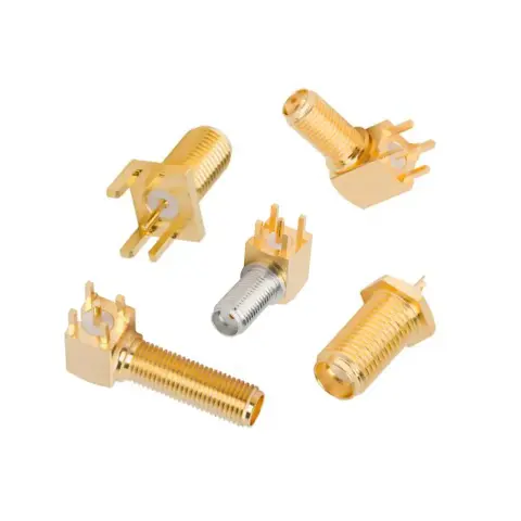

SMA female bulkhead panel mount connector

SMA Female Bulkhead Panel Mount Connector

Explore 50 Ω SMA female bulkhead panel mount connectors for secure installation through equipment panels, enclosures, and chassis. Part of the iPrece SMA Connector range, available products can be compared by mounting style, rear termination, frequency, panel dimensions, and environmental protection. Standard products and custom dimensions or terminations are available for different integration requirements.

Fast Production OEM Direct100% VNA tested 100% VNA Tested
45 Products
Part / DescriptionActionsbody-materialfrequency-maxvswr-maximpedanceinsertion-lossvoltage-rating
Details
BrassContact EngineeringTBD50 Ω0.06 dB335 Vrms
Details
Brass18 GHzTBD50 Ω0.06 dB335 Vrms
Details
Brass4 GHzTBD50 Ω0.06 dB335 Vrms
Details
Brass3 GHzTBD50 Ω0.06 dB335 Vrms
Details
Brass12.4 GHzTBD50 Ω0.06 dB335 Vrms
Details
Brass3 GHzTBD50 Ω0.06 dB335 Vrms
Details
Brass12.4 GHzTBD50 Ω0.06 dB335 Vrms
Details
Brass18 GHzTBD50 Ω0.06 dB335 Vrms
Details
Stainless Steel12.4 GHzTBD50 Ω0.06 dB335 Vrms
Details
Brass12.4 GHzTBD50 Ω0.06 dB335 Vrms

SMA Female Bulkhead Panel Mount Connector Specifications

An SMA female bulkhead mount connector provides a 50 Ω jack interface through an equipment panel, enclosure, or chassis. Products may share the same external SMA interface while differing in mounting construction, rear termination, dimensions, environmental sealing, and electrical performance.

Mounting and Panel Installation

The term chassis mount is also commonly used for bulkhead mounting, although the exact mechanical design may be a jam-nut bulkhead or a flange-mounted receptacle.

Mounting style

Panel attachment

Jam-nut bulkhead

Nut and washer

Two-hole flange

Two screws

Four-hole flange

Four screws

Field-replaceable flange

Flange and launcher

Front-mount and rear-mount describe the side from which the connector is installed. A round cutout may be sufficient for some products, while a D-shaped hole can prevent the connector from rotating during mating.

Rear Termination and Compatibility

The rear termination determines how the SMA female bulkhead panel mount connector connects to the equipment’s internal RF path. Cable dimensions, contact attachment, and installation method must match the selected connector.

Rear termination

Intended connection

Crimp/solder

Flexible coaxial cable

Direct solder

Semi-rigid or conformable cable

Solder cup or post

Internal RF connection

Through-hole pins

Printed circuit board

Field-replaceable contact

Microwave housing or launcher

Electrical, Mechanical, and Environmental Specifications

Specification

Available scope

Impedance

50 Ω

Frequency

Up to 18 GHz standard*

VSWR

Product- and frequency-specific

Orientation

Straight or right-angle

Body material

Brass or stainless steel

Body finish

Gold, nickel, or passivated

Mating durability

Product-specific

Temperature range

Product-specific

Environmental protection

Standard, IP-rated, or hermetic

*The maximum usable frequency depends on the complete connector configuration. Verify the specified frequency range and VSWR of the selected part.

SMA Female Bulkhead Mounting Considerations

Selecting a connector with the correct dimensions is only part of the installation. An SMA female bulkhead mount connector must also be positioned and secured so that mating forces, cable routing, and environmental sealing do not compromise the connection.

  • Mounting access: Confirm that tools can reach the nut or flange screws from the required side of the panel.

  • Rotation control: Use a D-shaped cutout, flange mount, or specified locking hardware to prevent movement during mating.

  • Ground continuity: Verify electrical contact between the connector body and chassis, particularly when panels are painted, coated, or anodized.

  • Internal clearance: Leave sufficient space for mounting hardware, the rear termination, and the cable’s minimum bend radius.

  • Strain relief: Prevent cable weight or movement from loading the solder joint, crimp, or connector body.

  • Environmental sealing: Install gaskets and O-rings against the specified panel surface and within the permitted compression range.

  • Installation torque: Follow the specified mounting and mating torque to avoid loosening the connector or damaging its interface.

SMA Female Bulkhead Connector Applications

SMA female bulkhead panel mount connectors create accessible RF connection points through equipment panels, enclosures, and chassis. The appropriate mounting, termination, and sealing configuration depends on the equipment design and operating environment.

Application

Function

Test equipment

Provides an external SMA test port

Antenna systems

Routes RF signals through an enclosure

RF modules

Connects internal circuitry to external equipment

Industrial systems

Supports secure panel-mounted connections

Aerospace and defense

Accommodates specialized flange or sealed designs

Outdoor equipment

Supports environmental protection with IP-rated models

Order Custom Bulkhead SMA Female Connectors

iPrece can support custom SMA female bulkhead connectors for requirements not covered by standard configurations. Use our custom RF cable assemblies tool to configure exact bulkhead or flange dimensions, cable-specific terminations, contact geometry, materials, and environmental sealing.

Existing parts can also be evaluated from a manufacturer part number, drawing, datasheet, or physical sample. Connectors may be supplied separately or integrated into a custom cable assembly. Provide the required frequency, panel dimensions, internal connection, operating environment, quantity, and documentation so iPrece can evaluate the appropriate design, testing, and production route.

SMA Female Bulkhead Panel Mount Connector FAQs

Are SMA bulkhead, panel-mount, and chassis-mount connectors the same? ↓
Panel mount is the broad term for connectors secured to a panel or enclosure. Bulkhead mount describes a through-panel construction, while chassis mount is commonly used for both bulkhead and flange-mounted receptacles.
What is the difference between a bulkhead connector and an SMA female-to-female bulkhead adapter? ↓
A bulkhead connector has an external SMA interface and a rear termination for cable, PCB, or internal wiring. A female-to-female bulkhead adapter provides mateable SMA female interfaces on both sides of the panel.
How do I choose between front-mount and rear-mount SMA connectors? ↓
Choose according to installation access, available internal clearance, preferred hardware position, and panel construction. Confirm the mounting side and assembly sequence from the product drawing.
Are all bulkhead SMA female connectors rated to 18 GHz? ↓
No. Maximum frequency and VSWR depend on the connector design, termination, materials, and installation. Check the electrical specifications of the selected product.
Can an SMA female bulkhead panel mount connector be supplied attached to coaxial cable? ↓
Yes, when a compatible cable termination is available. Specify the cable type, length, opposite connector, orientation, strain relief, and required electrical testing.