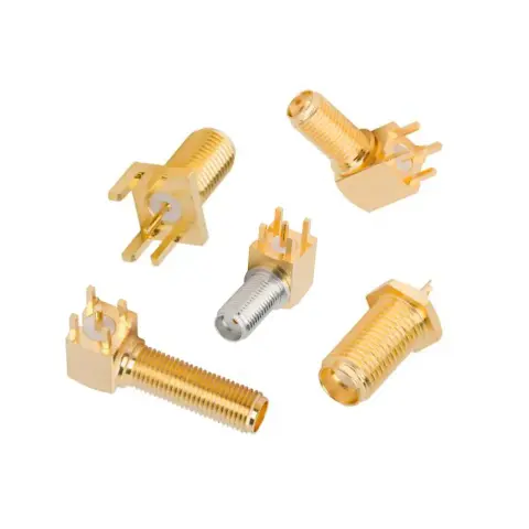



SMA Female Bulkhead Panel Mount Connector Specifications
An SMA female bulkhead mount connector provides a 50 Ω jack interface through an equipment panel, enclosure, or chassis. Products may share the same external SMA interface while differing in mounting construction, rear termination, dimensions, environmental sealing, and electrical performance.
Mounting and Panel Installation
The term chassis mount is also commonly used for bulkhead mounting, although the exact mechanical design may be a jam-nut bulkhead or a flange-mounted receptacle.
Front-mount and rear-mount describe the side from which the connector is installed. A round cutout may be sufficient for some products, while a D-shaped hole can prevent the connector from rotating during mating.
Rear Termination and Compatibility
The rear termination determines how the SMA female bulkhead panel mount connector connects to the equipment’s internal RF path. Cable dimensions, contact attachment, and installation method must match the selected connector.
Electrical, Mechanical, and Environmental Specifications
*The maximum usable frequency depends on the complete connector configuration. Verify the specified frequency range and VSWR of the selected part.
SMA Female Bulkhead Mounting Considerations
Selecting a connector with the correct dimensions is only part of the installation. An SMA female bulkhead mount connector must also be positioned and secured so that mating forces, cable routing, and environmental sealing do not compromise the connection.
Mounting access: Confirm that tools can reach the nut or flange screws from the required side of the panel.
Rotation control: Use a D-shaped cutout, flange mount, or specified locking hardware to prevent movement during mating.
Ground continuity: Verify electrical contact between the connector body and chassis, particularly when panels are painted, coated, or anodized.
Internal clearance: Leave sufficient space for mounting hardware, the rear termination, and the cable’s minimum bend radius.
Strain relief: Prevent cable weight or movement from loading the solder joint, crimp, or connector body.
Environmental sealing: Install gaskets and O-rings against the specified panel surface and within the permitted compression range.
Installation torque: Follow the specified mounting and mating torque to avoid loosening the connector or damaging its interface.
SMA Female Bulkhead Connector Applications
SMA female bulkhead panel mount connectors create accessible RF connection points through equipment panels, enclosures, and chassis. The appropriate mounting, termination, and sealing configuration depends on the equipment design and operating environment.
Order Custom Bulkhead SMA Female Connectors
iPrece can support custom SMA female bulkhead connectors for requirements not covered by standard configurations. Use our custom RF cable assemblies tool to configure exact bulkhead or flange dimensions, cable-specific terminations, contact geometry, materials, and environmental sealing.
Existing parts can also be evaluated from a manufacturer part number, drawing, datasheet, or physical sample. Connectors may be supplied separately or integrated into a custom cable assembly. Provide the required frequency, panel dimensions, internal connection, operating environment, quantity, and documentation so iPrece can evaluate the appropriate design, testing, and production route.