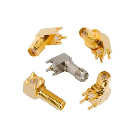


What Is an SMA Female Right Angle Connector?
An SMA female right angle connector combines a female SMA mating interface with an internal RF path that turns 90°. In standard polarity, the female interface has external threads and a center socket that mates with a standard SMA male connector.
The name does not identify the mounting or rear termination. Depending on the model, the connector may attach to a PCB, panel, terminal, or coaxial cable.
SMA Right Angle Female Connector Specifications and Configurations
SMA female right angle connectors share the same basic interface and body orientation, but their electrical ratings and installation requirements differ. Always verify part-specific specifications and drawings before selection.
SMA Female 90 Degree Connector Electrical Specs
Mechanical and Material Specifications
Mounting and Termination Configurations
Selecting the Right SMA Female 90 Degree Connector
The interface name alone does not define the complete part. Mounting, polarity, termination, footprint, materials, and frequency rating must also match the installation.
1. Check the Installed Mechanical Fit
The mating interface of an SMA female right angle connector is standardized, but PCB footprints, flange patterns, and installed envelopes are not necessarily interchangeable.
Verify:
Connector centerline above the PCB or panel
Through-hole or surface-mount footprint
Pin spacing and recommended land pattern
Board-edge setback
Panel thickness
Front- or rear-mount orientation
Flange dimensions and hole spacing
Flange clocking relative to the 90° body
Rear body clearance
Mating connector and coupling-nut clearance
Space for hand or torque-wrench access
Cable exit direction and bend radius
Use the dimensioned drawing or CAD model rather than judging orientation from a product photograph. Terms such as left, right, upward, or downward can change with the viewing direction.
2. Confirm Standard, Reverse-Polarity, or Reverse-Thread SMA
Standard SMA, RP-SMA, and reverse-thread SMA connectors are not interchangeable.
“Reverse polarity” refers to the center-contact arrangement, not the electrical signal polarity. RP-SMA female connectors can resemble standard SMA female connectors externally, so both the thread and center contact must be inspected.
3. Compare Right-Angle, Straight, and End-Launch SMA Connectors
End-launch connectors require close coordination with board thickness, transmission-line geometry, and launch design. A right-angle adapter can solve an existing routing problem, but it adds another mated interface and additional mechanical length compared to a dedicated SMA female right angle connector.
4. Avoid Common Selection Errors
Confusing SMA with RP-SMA: Verify the thread and center contact.
Assuming footprints match: Check the manufacturer’s drawing and recommended land pattern.
Inferring direction from images: Confirm the dimensioned orientation.
Using the family frequency rating: Verify the specification for the selected part.
Ignoring the mating envelope: Allow sufficient nut and wrench clearance.
Selecting the wrong cable version: Confirm the cable group and attachment method.
Overlooking panel alignment: Check the connector centerline and panel thickness.
SMA Female Right Angle Connector Applications
SMA right angle female connectors are used where a threaded RF interface must be positioned within a restricted mechanical envelope.
Typical applications include:
RF and microwave circuit boards
Wireless access points and gateways
Radios and communication modules
Antenna feed connections
Test and measurement equipment
Signal generators and analyzers
Industrial RF enclosures
Telemetry and monitoring equipment
Compact transmitters and receivers
Panel-mounted RF modules
Application suitability depends on the individual connector’s frequency, environmental, mechanical, and material specifications.
Custom and Cross-Reference Support
A standard catalogue SMA female right angle connector may not match every PCB footprint, panel opening, terminal position, or environmental requirement. Custom and modified configurations can be evaluated for:
Terminal length and geometry
PCB footprint requirements
Connector centerline
Panel and flange dimensions
Mounting-hole patterns
Body and contact materials
Plating and finish
Cable compatibility
Environmental sealing
Non-magnetic construction
Existing part-number replacement
Manufacturer cross-referencing
For cable-based requirements, configure the selected connector using our SMA cable assembly tool to define the required cable, length, and opposite-end termination.