Why Cable-Loss Correction Does Not Restore Antenna-Test Dynamic Range

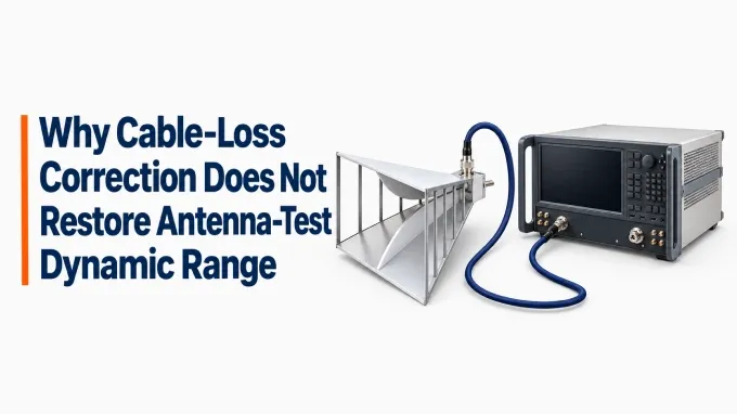
Cable-loss correction compensates the reported antenna response for interconnect attenuation. It does not improve the signal-to-noise ratio (SNR) acquired by the receiver. Weak responses may still lie too close to the noise floor for accurate measurement. To preserve enough margin, set a maximum interconnect-loss budget for the weakest response you need to measure, then reduce physical loss to meet it.
Why cable-loss correction leaves weak responses near the noise floor
The interconnect attenuates the signal before it reaches the receiver input. The receiver adds noise to that attenuated signal, and the correction then rescales the measurement to represent the response at the receiving connector.
The correction scales both the measured signal and the receiver-added noise. When that noise is referred back to the receiving connector, its level rises along with the signal estimate. Their ratio does not improve. The equivalent noise floor at that connector therefore increases, even though the receiver’s physical noise floor stays the same.
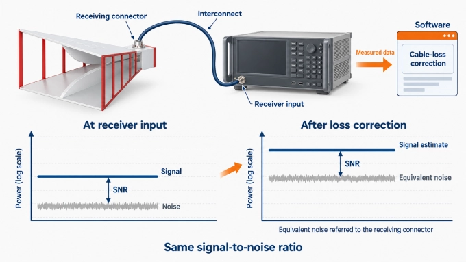
The receiver’s intrinsic dynamic-range specification can remain unchanged while the test loses usable measurement range. With source power and receiver settings fixed, interconnect loss reduces the separation between the received main-beam signal and the noise floor. A clear main beam can therefore coexist with sidelobes or cross-polarized responses that are too weak to measure accurately.
Calibration remains valuable because it corrects systematic amplitude and phase errors. Normalizing the pattern to its main-beam peak changes the scale, but it also leaves weak-response SNR unchanged.
Calculate the maximum interconnect loss your test can tolerate
The maximum interconnect loss is the weakest required signal power minus the receiver noise floor and the margin needed for the measurement. Treat this result as the loss limit for the full path from the receiving connector to the receiver input.
: weakest required signal power at the receiving connector, in dBm.
: receiver-input RMS noise power over the selected measurement bandwidth, in dBm.
: required SNR plus engineering reserve, in dB.
For a direct far-field pattern measurement, subtract the required pattern span from the peak received power to obtain . Choose the required SNR from the uncertainty you can allow from receiver noise. For coherent amplitude measurements, the following high-SNR approximation gives the uncertainty from noise alone at approximately 95% confidence (coverage factor 2). It assumes additive Gaussian noise with equal, independent in-phase and quadrature components and negligible reference-channel noise:
Express the uncertainty as plus or minus the calculated value. SNR is expressed in dB and uses signal power divided by total mean noise power. Applying this approximation gives about ±1.2 dB at 20 dB SNR; limiting the noise contribution to ±0.5 dB requires about 28 dB SNR. These values are calculated using the Gaussian-noise model described by Gu et al. Other errors share the total uncertainty allowance, and engineering reserve is added separately when forming .
Calculate the allowance across the operating band and use the smallest result. To specify a replacement assembly, subtract the losses of components that will remain outside it, such as a switch or rotary joint. Compare the remaining allowance with the assembly’s measured end-to-end loss, which already includes its connectors.
If you calculate loss from bare-cable attenuation, include connector losses separately. Dividing the cable-only loss allowance by attenuation per metre also gives an approximate maximum cable length.
This budget assumes a passive receive path with a substantially fixed noise floor dominated by the receiver. The worked calculation applies directly to far-field pattern samples. For near-field measurements, determine the required probe-sample SNR through an analysis of how measurement noise affects the reconstructed far-field pattern. A desired far-field sidelobe depth cannot simply be subtracted from the near-field peak.
A receiving chain that includes an LNA or frequency converter needs a budget that also accounts for its gain, noise contribution, and the losses before and after it.
Worked example: replacing a 12 dB path to meet a 7 dB budget
The existing path needs at least 5 dB less loss in this hypothetical example. A replacement with 6 dB total loss meets the budget.
Assume the peak received power at the receiving connector is −30 dBm, and the test must measure responses 60 dB below that peak. The weakest required signal is therefore −90 dBm. With a receiver noise floor of −120 dBm, a required SNR of 20 dB, and a 3 dB engineering reserve, the allowance is:
Total path loss | Weak signal at receiver | SNR | Meets the budget? |
12 dB | −102 dBm | 18 dB | No |
6 dB | −96 dBm | 24 dB | Yes |
The replacement removes 6 dB of loss and leaves 1 dB of unused allowance. Both measurements can be corrected to the same nominal −90 dBm response, while their SNRs remain different.
Choose how to recover the required measurement margin
Choose the least disruptive change that achieves the required measurement margin while preserving the movement, access, and serviceability the test requires.
Remedy | Choose it when… | Main tradeoff |
Shorten the run and remove unnecessary adapters | Routing changes can recover enough loss without restricting movement. | Preserve service loops, strain relief, and access for maintenance. |
Use a lower-loss assembly | The required length cannot change, but a different assembly can meet the allowance. | The cable may be thicker, heavier, and less flexible, with a larger minimum bend radius. |
Move the receiver or conversion hardware closer | Practical cable options cannot meet the loss allowance. | The new arrangement must support synchronization, calibration, and physical access. |
Keep the antenna separation and scan geometry unchanged when relocating electronics. Positioning a receiver or suitable downconverter near the receiving antenna or probe shortens the path carrying the high-frequency RF signal.
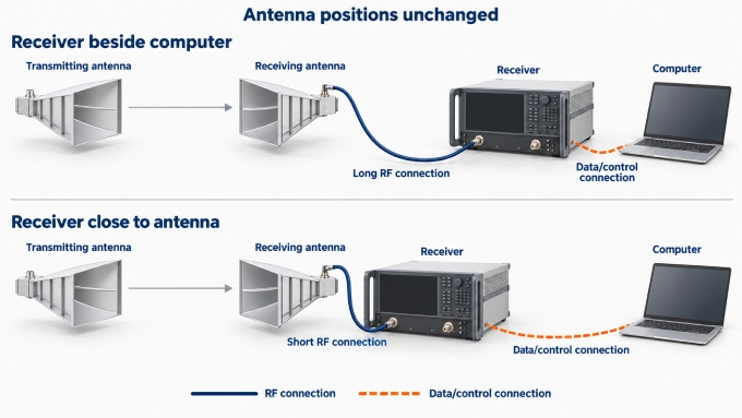
For configurations with an LNA or different conversion hardware, use the complete-chain budget described above. The RF cable loss removed is only one contributor to the net change in sensitivity.
Narrower IF bandwidth or coherent averaging can reduce noise, but increase acquisition time. More source power or a suitable low-noise preamplifier can also help, provided the strongest response stays within the chain’s linear range. A preamplifier before the long cable can limit the cable’s effect on system sensitivity. An amplifier after the cable may help overcome downstream receiver noise, but it cannot reverse the SNR degradation already introduced by the cable.
Confirm that the change improved the weak-response measurement
Judge the change by the margin achieved for the weak response, rather than by the corrected amplitude alone.
Repeat the measurement. Recalibrate for the changed path, then repeat the weak-response measurement with the same source power, acquisition settings, and antenna geometry.
Compare the received signal and noise. Examine the raw receive level and noise floor before and after the change. For a cable-only change with a substantially unchanged receiver noise floor, the improvement in signal margin should approximately match the loss removed.
Confirm that the result meets the requirement. The weak response should now clear the noise floor by the planned margin, while the strongest response remains within the chain’s linear range.
If the improvement falls short, leakage, multipath, or instability may be setting the limit. Investigate those alternatives then; improved repeatability alone does not establish accuracy.
Meet the loss budget with iPrece ULX, VNX, or a custom RF cable assembly
Use your remaining assembly-loss allowance to narrow iPrece’s cable options, then choose the length and connector configuration that fits the installation. Base the final selection on the finished assembly’s performance across the operating band, including the effect of any movement during testing.
iPrece option | Role in the selection |
Evaluate ultra-low-loss cable models against the attenuation allowance at the required frequency and length. | |
Consider these precision VNA test cables when phase stability and repeatability during cable movement matter alongside insertion loss. | |
Configure the cable, finished length, and connector interfaces around the installation, with a maximum end-to-end assembly loss. |
To request an assembly recommendation, send iPrece the frequency band, maximum allowable assembly loss, finished length, connector interfaces, and whether the cable will remain fixed or move during testing. Ask for insertion-loss and return-loss data for the proposed configuration. If the lead will flex during a scan, describe the movement so the recommendation can also address amplitude and phase stability.
FAQ
Discussion (0)
Be the first to comment.