Real-Life Applications of Low Pass Filters

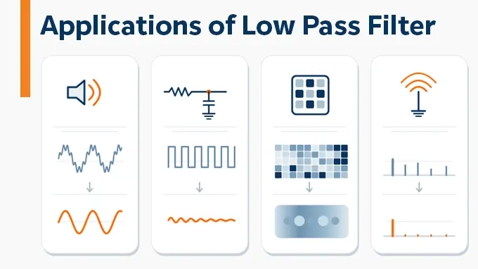
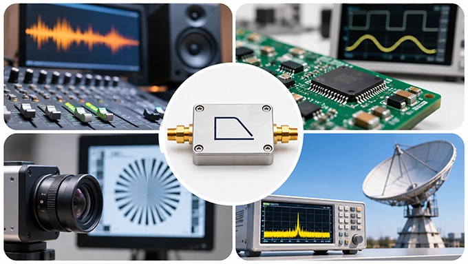
The primary applications of low pass filters (LPFs) span across various engineering disciplines, including:
RF transmitter harmonic suppression and spurious emission control
IF extraction and frequency conversion in superheterodyne receivers
Cryogenic noise filtering in quantum computing hardware
Anti-aliasing for ADCs and power supply ripple smoothing
Digital image smoothing and high-frequency noise reduction
Subwoofer crossovers and audio signal processing
Although these applications utilize vastly different hardware technologies—from discrete LC networks to distributed microstrip lines—they all solve a fundamental engineering problem: preserving essential low-frequency information while rejecting unwanted higher-frequency spectral components. What varies is the operating frequency regime, the required roll-off steepness, and the hardware constraints.
What Is a Low Pass Filter Used For? (Application Examples)
A low-pass filter is used whenever the information of interest occupies a lower frequency range than the unwanted signal components.
Four practical low pass filter application examples are:
Separating bass frequencies for a subwoofer
Smoothing noise in a digital image
Removing switching interference from a sensor voltage
Suppressing transmitter harmonics in an RF signal chain
In each case, the filter must preserve the information the system needs. A subwoofer crossover should not remove useful bass, just as an RF filter must not attenuate the intended carrier excessively.
This makes the cutoff frequency and transition behavior important even when the application does not require a detailed mathematical filter design.
When to Use Low Pass vs. High Pass Filter?
Use a low-pass filter when the wanted signal is below the unwanted frequency range. Use a high-pass filter when the opposite is true.
Application | Suitable Filter | Primary Function |
RF transmitter harmonics | Low-pass | Attenuates spurious emissions and harmonics above the carrier |
ADC input conditioning | Low-pass | Acts as an anti-aliasing filter before signal sampling |
Removing DC from an RF/AC signal | High-pass | Acts as a DC blocking capacitor, passing only the high-frequency AC |
Selecting a specific RF channel | Band-pass | Rejects out-of-band frequencies on both sides of the center frequency |
Subwoofer signal routing | Low-pass | Blocks directional mid/high-frequency audio |
Microphone rumble removal | High-pass | Removes unwanted low-frequency mechanical vibrations (wind/handling noise) |
A common design oversight is selecting a low-pass filter simply because a system is "noisy." The correct topology dictates that the filter choice must align strictly with the frequency domain relationship between the signal of interest and the noise floor.
Low Pass Filter Audio Applications (Music & Amplifiers)
Audio is one of the most familiar examples of a low pass filter application.
Low-frequency information includes bass guitar fundamentals, kick-drum energy, and the lower portion of many instrument sounds. High-frequency information contributes brightness, attack, detail, and certain types of noise.
A low-pass filter adjusts this balance by progressively attenuating frequencies above its cutoff.
Subwoofer & Car Audio Settings
A low pass filter on a subwoofer prevents it from reproducing much of the midrange and high-frequency content intended for the main speakers.
In a car-audio system, the LPF may be implemented in an amplifier, head unit, or digital signal processor. A low pass filter subwoofer board performs a similar frequency-separation function in an electronic crossover.
For a typical car-audio setup, approximately 80 Hz is a reasonable initial crossover setting, but it is not a universal optimum. The final setting depends on the main speakers' bass response, the crossover slope, the subwoofer's acoustic response, and its placement.
For example, setting a subwoofer LPF around 80 Hz and coordinating it with the main speakers' high-pass crossover can establish a useful starting point. The combined acoustic response must still be checked for excessive overlap or a dip near the crossover.
Note: Avoid applying independent, uncoordinated low-pass filters at several stages. Their slopes and phase shifts can combine, moving the effective crossover away from the intended setting.
Software Mixing: Audacity & Ableton
In music production, a common low pass filter application involves tonal shaping, automated transitions, and reducing unwanted high-frequency content.
Audacity: Select the desired audio region and open Effect > EQ and Filters > Low-Pass Filter. Adjust the cutoff frequency and roll-off to reduce the higher-frequency content. This can soften excessive brightness or reduce high-pitched noise.
Ableton Live: The Auto Filter device includes a low-pass mode with adjustable cutoff and resonance. Its modulation capabilities also support moving filter effects, commonly used in electronic music production.
These applications extend beyond subwoofers. A low pass filter on vocals can produce a darker or more distant sound, while a low pass filter on a microphone recording may reduce some high-frequency hiss.
However, a low-pass filter also removes legitimate upper harmonics and consonant detail. It is not a general-purpose solution for all background noise. Low-frequency rumble usually requires high-pass filtering, while narrowband interference may call for a notch filter.
The same frequency-selective principle becomes useful in images, except that the frequencies describe changes across space rather than changes over time.
Application of Low Pass Filter in Image Processing
In image processing, a low-pass filter suppresses high spatial frequencies—rapid changes in image intensity over short distances. These components include fine textures, sharp transitions, and certain forms of image noise.
Low spatial frequencies represent broader, slowly changing features such as large areas of brightness or color.
Common types of low pass filter in image processing include Gaussian smoothing, box averaging, and frequency-domain low-pass filtering.
Image Smoothing and Noise Reduction
Consider a digital photograph containing fine-grained noise.
Applying a Gaussian low-pass filter reduces rapid pixel-to-pixel variations, making the image appear smoother. The trade-off is that genuine fine detail is also attenuated.
For example, stronger filtering may make a noisy wall look cleaner while simultaneously softening hair, text, or small architectural features. This is why any application of low pass filter techniques on an image must balance noise suppression against detail preservation.
Median filters are also used for image noise reduction, but they are nonlinear spatial filters and should not be treated as identical to conventional linear low-pass filters.
Anti-Aliasing & Blurring in Camera Sensors
A camera can include an optical low-pass filter (OLPF) directly in front of its image sensor.
Its purpose is to reduce spatial frequencies that the sensor's sampling grid cannot represent faithfully. Without adequate optical suppression, fine repeating patterns can create moiré and false-color artifacts. An optical low-pass filter deliberately reduces some fine image detail before sampling, trading a degree of sharpness for lower aliasing risk.
Not every modern digital camera includes an OLPF. Some designs omit it to maximize perceived sharpness, relying partly on high sensor resolution and subsequent image processing.
Digital blurring after capture serves a different purpose: it can smooth an image or prepare it for downsampling, but it cannot reliably reconstruct detail already corrupted by aliasing at capture.
How Does Low-Pass Filtering Affect Digital Radiographic Images?
The application of low pass filter technology in digital radiography involves a particularly important trade-off.
Smoothing can reduce visible image noise and improve apparent uniformity. However, it can also reduce the visibility of small structures and fine edges. For example, excessive Gaussian smoothing may suppress noise while reducing spatial resolution and the visibility of diagnostically relevant details.
The result should therefore be evaluated using image-quality measures such as noise characteristics and the modulation transfer function (MTF), rather than judging the image only by how smooth it looks. The objective is not maximum noise reduction. It is preserving diagnostically useful information at an acceptable noise level.
Application of Low Pass Filter in Electronics & Circuits
In electronics, low-pass filters perform many of the same operations as digital image filters, but on electrical voltage and current waveforms.
Typical applications include stabilizing sensor readings, conditioning ADC inputs, smoothing power converter outputs, and removing unwanted switching components.
RC Low Pass Filter Applications
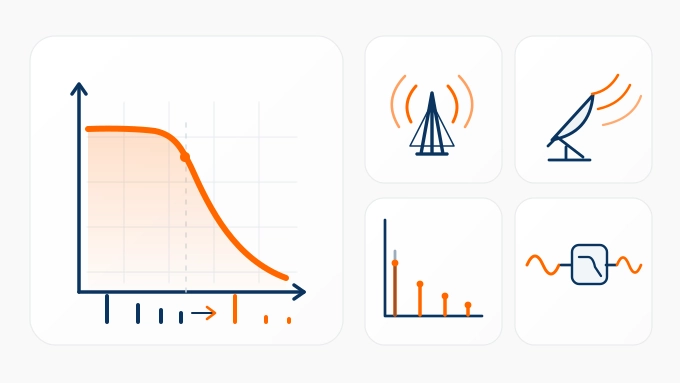
The simplest application of a passive low pass filter uses a resistor in series with the signal and a capacitor connected from the output to ground.
For an ideal, lightly loaded RC circuit, the cutoff frequency is:
Consider a sensor output filtered using:
The nominal cutoff frequency is approximately 15.9 Hz.
This circuit can attenuate high-frequency interference while preserving slowly varying sensor information. However, it also slows the response to genuine changes in the measured quantity.
An RC low-pass filter is useful for temperature sensors, slowly varying control voltages, and similar low-bandwidth signals. Its suitability for an ADC input depends on the converter's input impedance, sampling behavior, and acquisition time.
Active vs. Passive Low Pass Filter Applications
The choice between active and passive filter topologies depends heavily on the operating frequency, signal amplitude, insertion loss tolerance, and required Q-factor.
Implementation | Typical Application | Key Engineering Consideration |
Passive RC (First-order) | Sensor smoothing, basic noise suppression | Load-dependent response; strictly for low-frequency/DC applications. |
Active (Op-Amp Based) | Audio circuits, low-frequency ADCs | Provides gain and buffering; limited by Op-Amp bandwidth (GBP) and noise. |
Passive LC (Lumped Elements) | Power supplies, VHF/UHF RF paths | Relies on component Q-factor; highly susceptible to parasitic SRF at higher frequencies. |
Distributed Elements (Microstrip/Stripline/Cavity) | Microwave and mmWave RF systems | Used when lumped LC components fail due to parasitics. Offers high power handling and precision at gigahertz frequencies. |
In low-frequency regimes, an active low-pass filter is advantageous because it can combine steep attenuation with passband gain without inductor-related bulk. However, in RF and microwave engineering, op-amps lack the required bandwidth and power handling. Therefore, high-frequency applications rely exclusively on passive LC networks or, moving into the GHz range, distributed physical structures like stepped-impedance microstrip filters and resonant cavities.
Anti-Aliasing and Power Supply Filtering
Before an analog-to-digital converter samples an electrical signal, unwanted high-frequency components may need attenuation.
If an out-of-band signal aliases into the wanted frequency range, digital processing cannot reliably distinguish it from legitimate sampled information. An analog anti-aliasing low-pass filter therefore reduces problematic frequencies before conversion.
Not every ADC architecture requires the same external filtering: some converters incorporate substantial alias rejection internally. Low-pass filtering is also used after switching power stages. An LC network can attenuate switching-frequency components while allowing the intended DC or low-frequency output to reach the load.
These circuits must be designed with source and load conditions in mind, particularly where filter resonance could affect regulation stability.
Filtering Noise in Oscilloscopes & Multimeters
A common low pass filter application in oscilloscopes, often labeled Bandwidth Limit, reduces the instrument's effective measurement bandwidth.
This can make low-frequency waveforms easier to observe by reducing displayed high-frequency noise. However, bandwidth limiting can conceal fast edges, overshoot, or high-frequency interference that the engineer actually needs to measure.
Certain digital multimeters also include low-pass filtering for measuring variable-frequency-drive outputs. By suppressing high-frequency PWM switching components, the instrument can provide a more useful reading of the lower-frequency motor-drive voltage.
The filter must not be used to conclude that a hazardous high-frequency voltage is absent. These examples lead naturally to RF engineering, where unwanted high-frequency content can affect not just a measurement but the operation of an entire radio system.
Critical Applications of Low Pass Filters in RF & Microwave
In RF systems, filtering targets signals that span from the kilohertz range up to millimeter-wave frequencies. An RF low pass filter is indispensable when the desired carrier, modulation envelope, or down-converted IF resides below problematic high-frequency spurious products.
Harmonic Suppression in RF Transmitters
Nonlinearities in RF Power Amplifiers (PAs) inevitably generate harmonic components at integer multiples of the fundamental operating frequency.
For instance, a transmitter heavily driving a PA at 900 MHz will generate unwanted spectral energy at:
1.8 GHz (Second harmonic)
2.7 GHz (Third harmonic)
A low-pass filter cascaded immediately after the PA ensures the fundamental 900 MHz carrier passes with minimal insertion loss, while providing deep rejection at the harmonic frequencies. This is a strict regulatory requirement for passing FCC/CE emission standards. The core engineering challenge here is balancing a low passband insertion loss (to preserve transmit power and efficiency) against sufficient stopband attenuation, while handling the PA's peak thermal loads.
IF Extraction in Superheterodyne Receivers
Superheterodyne architectures utilize an RF mixer and a Local Oscillator (LO) to down-convert an incoming RF signal to an Intermediate Frequency (IF). Mathematically, an ideal mixer outputs both the sum and difference of the input frequencies.
For example:
Parameter | Frequency |
RF input | 110 MHz |
Local Oscillator (LO) | 100 MHz |
Difference Product (Target IF) | 10 MHz |
Sum Product (Spurious) | 210 MHz |
To isolate the 10 MHz baseband/IF signal, a low-pass filter is deployed post-mixer to cleanly pass the difference product while heavily attenuating the 210 MHz sum product and any LO leakage. While band-pass filters are also common for IF extraction, low-pass topologies are highly effective when the IF is close to DC (Direct Conversion or Zero-IF architectures).
Quantum Computing Applications (Ultrawide Stopband)
Superconducting quantum processors operate at extremely low temperatures, where unwanted electromagnetic radiation can degrade sensitive quantum states.
High-frequency noise entering through electrical connections may contribute to excess excitation, heating, or quasiparticle generation. Low-pass filtering can suppress unwanted high-frequency energy on suitable control and bias lines.
Unlike a conventional low pass filter application, some cryogenic systems need rejection extending far beyond the signal frequencies being passed.
A 2023 study by Robert Rehammar and Simone Gasparinetti demonstrated a low-pass filter based on a leaky coaxial waveguide.
The reported prototype exhibited:
Less than 0.15 dB insertion loss up to 10 GHz
More than 60 dB attenuation above 70 GHz
S-parameter measurements extending to 145 GHz
These results demonstrate the importance of an ultrawide stopband: a filter that rejects nearby unwanted frequencies may still leak substantially higher-frequency radiation through parasitic paths. However, this approach is not interchangeable with every qubit-control filter.
Some microwave control lines must deliberately transmit gigahertz signals to the qubits, while DC and flux-bias lines have different bandwidth requirements.
Filtering, thermalization, attenuation, and cryogenic compatibility must be engineered together. No individual low-pass filter eliminates every source of thermal noise.
The Hardware Reality: Connectors in RF Filter Modules
In simulation software, a low-pass filter exhibits an ideal mathematical roll-off. In physical RF hardware, however, that response is heavily degraded by PCB parasitics, component Self-Resonant Frequencies (SRF), and the electromagnetic environment.
A lumped-element filter that shows excellent theoretical rejection at 3 GHz might completely fail in reality if the capacitors act as inductors past their SRF. Furthermore, integration mismatch can cause unexpected passband ripple and severe insertion loss.
Physical connection interfaces must be matched to the operating wavelength. Standard SMA connectors are suitable for many RF applications up to 18 GHz, whereas precision 2.92 mm or 2.4 mm interfaces are mandatory for mmWave modules to avoid introducing unwanted parasitic capacitance or cavity resonances within the connector itself. In sensitive cryogenic setups, engineers must also specify non-magnetic connectors to prevent localized magnetic interference. Ultimately, the real-world application of low pass filter designs must be evaluated via Vector Network Analyzer (VNA) S-parameter measurements (S11 and S21) of the fully assembled interconnect, not just mathematical models.
FAQ
Discussion (0)
Be the first to comment.