What Is the Maximum Voltage That a Coaxial Cable Can Deliver to RF Equipment?

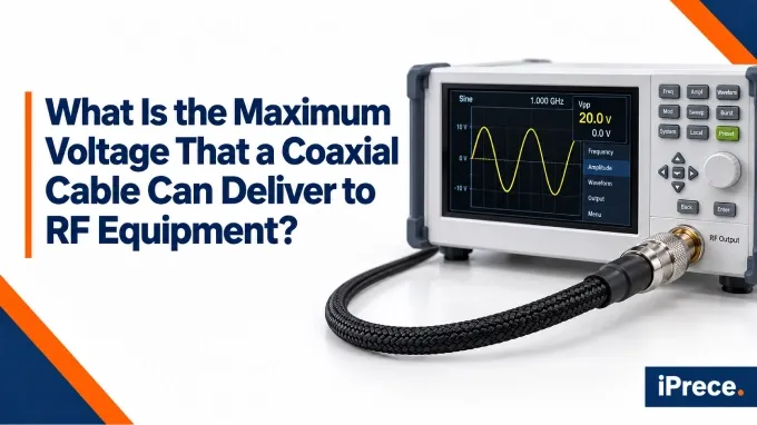
For common RF coaxial cables, maximum working voltage is often in the 1000 to 4000 V range, depending on the exact cable. As practical examples, some RG-58 cables are rated around 1400 to 1900 V, while some RG-213 cables are rated around 3700 V. Specialized high-voltage coaxial cables can be rated for much more.
With that said, there is no single maximum voltage for all coaxial cables. The aforementioned numbers are useful as rough reference points, but they should not be treated as universal ratings for every RG-58 or RG-213 cable. Different manufacturers and constructions can have different limits.
Typical Coaxial Cable Voltage Ratings
Typical coaxial cable voltage ratings vary considerably by cable size and construction. Smaller flexible RF cables may be rated around 1 kV, while larger coaxial cables can reach several kilovolts. The examples below provide a quick comparison of specific manufacturer-rated cables.
These figures are useful for comparison, but RMS operating ratings and DC voltage-withstand ratings are not identical specifications. For actual equipment design, use the voltage specification and test conditions in the datasheet for the exact cable part number.
What Causes Voltage Breakdown in a Coaxial Cable Assembly?
Voltage breakdown occurs when the electric field somewhere in the cable assembly exceeds the capability of the surrounding dielectric or air gap. The published RF voltage rating therefore depends not only on the bulk cable insulation but also on conductor geometry, connector transitions, assembly quality, and operating conditions.
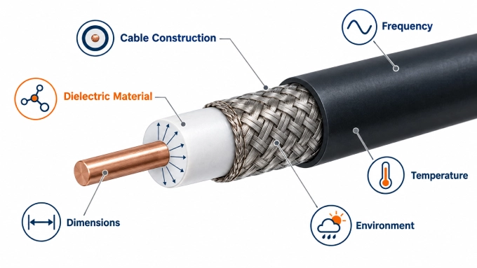
1. Cable Construction and Dielectric
The spacing between the inner and outer conductors, cable diameter, and dielectric strength influence the maximum voltage before breakdown. Air gaps at connector transitions may also break down before the cable dielectric itself.
2. VSWR and Impedance Mismatch
An impedance mismatch reflects part of the incident signal. The incident and reflected waves combine to create local voltage and current peaks along the cable. These peaks can cause dielectric breakdown or concentrated heating even when the forward power appears to remain within the cable’s nominal rating. Higher coaxial cable VSWR therefore requires appropriate power derating.
3. Peak Power and Maximum RF Voltage
Peak power determines the highest instantaneous RF voltage inside the cable. For pulsed or modulated signals, the applicable peak power or peak envelope power—not merely the average power—must be considered when checking the cable and connector voltage limits.
A low duty cycle may reduce average heating, but it does not eliminate the electrical stress created by the peak voltage. Arcing or dielectric breakdown can therefore occur during a short pulse even when the average power remains relatively low.
5. Temperature, Altitude, and Installation Condition
Reduced atmospheric pressure at altitude can also lower the flashover margin at air-filled connector interfaces.
Moisture, contamination, tight bends, crushed dielectric, worn connectors, and incorrect termination can create impedance discontinuities or concentrated electric fields. Consequently, a damaged or poorly assembled cable may fail below the published RF coaxial cable voltage rating.
Can the Connector Limit Voltage Before the Coaxial Cable Does?
Yes. A coaxial connector can reach its voltage or RF power limit before the cable itself does. The usable rating of a custom RF cable assembly therefore cannot be determined from the bulk cable specification alone.
Can the Connector or RF Equipment Reach Its Voltage Limit First?
Yes. A coaxial cable may have a higher voltage rating than the connectors, adapters, or equipment connected to it. The safe voltage for the complete RF path is therefore determined by the lowest applicable working-voltage limit—not by the bulk cable specification alone.
Cable Versus Connector Voltage Ratings
Connectors have their own working-voltage and dielectric-withstanding-voltage specifications. Working voltage defines the intended operating limit, while dielectric-withstanding voltage describes a test threshold and should not be treated as a permissible continuous voltage.
The following manufacturer-published figures illustrate how the two specifications may differ:
These are examples from one manufacturer’s connector series, not universal ratings for every variation of these connectors. Always verify the datasheet for the exact connector part number used in the assembly.
RF Equipment Maximum Input Rating
The cable’s voltage capability does not determine how much voltage the connected RF equipment can safely accept. Amplifiers, receivers, attenuators, matching networks, and other components have their own maximum input ratings, which may be lower than those of the cable and connectors.
The complete RF path should be operated below the lowest applicable working-voltage limit with an appropriate engineering margin.
FAQ
Discussion (0)
Be the first to comment.