What Is VSWR in RF Systems?

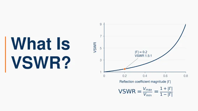
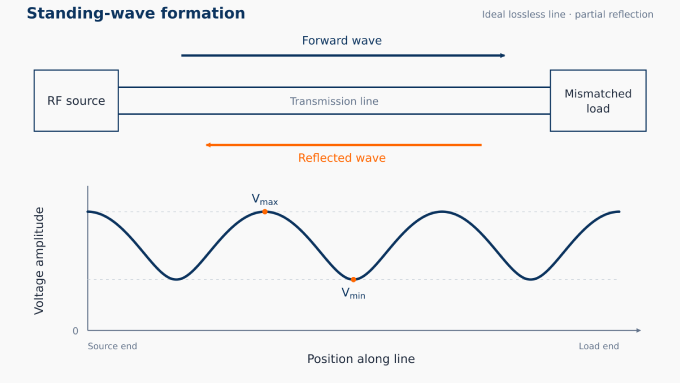
VSWR, or voltage standing wave ratio, is the ratio of the maximum to minimum voltage amplitude in the standing-wave pattern on an ideal lossless transmission line. These amplitudes describe the RF voltage envelope at different positions along the line.
VSWR is dimensionless and commonly written as a ratio:
1:1: The maximum and minimum amplitudes are equal, indicating no reflected wave.
Above 1:1: Reflection produces amplitude variation along the line. A VSWR of 2:1 means the maximum voltage amplitude is twice the minimum; higher values indicate greater mismatch.
In RF specifications, the value applies at a stated frequency and reference plane, relative to a defined impedance, commonly 50 Ω.
How Does Impedance Mismatch Create Standing Waves?
Reflection occurs when the load impedance differs from the coaxial cable characteristic impedance. Characteristic impedance describes the voltage-to-current ratio of a travelling wave, while load impedance describes that relationship at the load terminals.
At this boundary, the incident wave alone cannot provide the voltage-to-current ratio required by the load. A reflected wave forms and travels back toward the source so that the total voltage and current meet that requirement. Impedance discontinuities at connectors and other transitions can also cause reflections.
For a steady sinusoidal signal on a lossless line, the incident and reflected voltage waves combine according to their relative phase:
In phase: Their amplitudes add, producing a voltage-amplitude maximum.
180° out of phase: Their amplitudes subtract, producing a voltage-amplitude minimum.
Their relative phase varies along the line. At a fixed frequency and stable load, the maxima and minima remain at fixed positions, while the RF voltage at each point continues to oscillate in time. This fixed voltage-amplitude pattern is called a standing-wave pattern.
What Is VSWR vs SWR?
SWR stands for standing wave ratio, a general term that can be defined using voltage or current amplitudes. VSWR specifically refers to voltage amplitudes. On an ideal lossless transmission line, the voltage and current standing-wave ratios have the same numerical value.
In RF antenna and feedline specifications, SWR commonly means VSWR. For example, an antenna rated at “SWR 2:1” generally has the same stated matching requirement as one rated at “VSWR 2:1.” The terminology usually reflects a naming convention rather than a different RF performance metric.
How to Calculate VSWR
The VSWR formula uses the magnitude of the voltage reflection coefficient at the frequency and reference plane of interest.
VSWR formula:
Here, and are the maximum and minimum standing-wave voltage amplitudes on a lossless line. The reflection coefficient, , is the complex ratio of the reflected voltage wave to the forward voltage wave. Only its magnitude, , enters the calculation; the reflection phase is not retained in the VSWR result.
Use a linear coefficient magnitude, not its dB value or a reflected-power fraction. The standard relationship assumes a real reference impedance and a passive load.
If the load impedance is known, first calculate the reflection coefficient at the load:
Here, is the load impedance at the frequency of interest, including any reactance, and is the line’s real characteristic impedance, such as 50 Ω. Calculate the complex reflection coefficient, then substitute its magnitude, , into the VSWR formula above.
VSWR can also be calculated from measured forward and reflected power:
Here, is forward power and is reflected power. Use values measured at the same reference plane and expressed in the same linear units, such as watts—not dBm. These relationships assume a real reference impedance and a passive load.
For example, if the reflected voltage-wave amplitude is 20% of the forward amplitude:
The result is conventionally written 1.5:1 . The reflected-power fraction is , so this example gives of the incident power is reflected at the same reference plane.
VSWR and return loss express the same reflection magnitude as a ratio and a dB value, respectively. S11 is the complex input reflection coefficient and also includes phase. For the relationship and conversion between the ratio and dB representations, see the difference between VSWR and return loss.
What Does VSWR Tell You About an RF Cable Assembly?
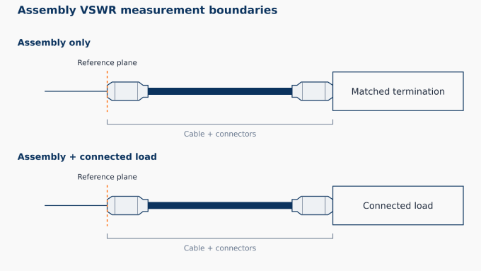
For custom RF cable assemblies, VSWR describes the input match of the complete interconnect under specified conditions. The response includes the cable, connectors, mating interfaces, and cable-to-connector transitions.
A 50-ohm coaxial cable designation identifies the cable’s nominal characteristic impedance. A connector’s published VSWR applies to its specified test configuration. Neither establishes the finished assembly’s VSWR: combining the components introduces transitions whose electrical performance depends on how they are integrated.
To characterize the assembly alone, its opposite end is terminated with a load matched to the reference impedance. Connecting an antenna or another device instead makes that load part of the measured response. The result then describes the assembly and connected load together, so termination conditions matter when interpreting or comparing assembly VSWR values.
How High VSWR and Low VSWR Affect the RF System
Lower VSWR indicates a smaller reflected-power fraction; its acceptable limit depends on the application and operating conditions.
High VSWR: For a fixed incident power at the load, increased reflection reduces the power it accepts. Reflections between mismatched stages can also produce transmission or gain ripple. In transmit systems, mismatch may trigger amplifier foldback or impose excessive voltage and current stress. The risk depends on RF power, frequency, reflection phase, and protection design.
Low VSWR: A low value indicates a close impedance match at the stated plane and frequency, but does not establish how efficiently an antenna radiates the accepted power. Shielding effectiveness and susceptibility to radio frequency interference in RF systems require separate assessment.
Acceptable VSWR: Use the specified maximum across the operating band, together with the system’s reflection allowance, RF power, source/load requirements, and agreed test conditions. Passing at one frequency does not establish compliance across the band. Apply the project’s acceptance margin; an antenna and a precision test interconnect need not share the same limit.
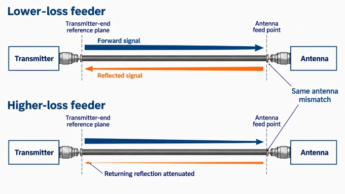
Interpretation limits: A lossy feeder attenuates the returning reflection, so input VSWR can look better than the match at the antenna while less power reaches it. Because VSWR discards the reflection phase, the ratio alone cannot identify a unique load impedance or locate the mismatch. Different faults can therefore produce the same VSWR.
How to Reduce VSWR in RF Systems
Reduce VSWR by correcting the underlying mismatch. First establish whether it comes from the load, incompatible impedances, or an interconnect defect.
Match nominal impedances: Select electrically compatible cable, connectors, adapters, and equipment ports. Review 50-ohm vs 75-ohm coaxial cable when assessing substitutions, since an unmatched impedance transition introduces reflection.
Preserve termination geometry: Use connectors designed for the cable’s dimensions and construction. Replace damaged cable or correct defective terminations that disturb the intended RF geometry.
Mate connectors correctly: Inspect and clean interfaces using the approved method, replace damaged connectors, and fully engage compatible mating parts. Follow the manufacturer’s SMA connector torque specification.
How to Reduce VSWR in an Antenna
Confirm band and feed compatibility: Select an antenna designed for the operating frequencies and intended feed impedance. Check its specified matching requirements before substituting the feeder or antenna.
Evaluate the installed configuration: Assess the antenna with its intended mounting, ground-plane arrangement, and clearances. Nearby conductive structures can alter coupling and shift feed-point impedance, so a bench-tested match may not represent installed conditions.
Adjust the antenna or feed-point matching: Where the design permits, adjust its tuning parameters or use suitable feed-point matching. Check the resulting match across the intended operating band. Assess radiation efficiency separately.
VSWR Testing & Measurement
A VSWR test typically uses a calibrated VNA or cable-and-antenna analyzer to measure reflection across the operating band and display the corresponding VSWR. On an operating transmit path, a directional coupler with suitable power sensors can instead determine VSWR from forward and reflected power.
A meaningful result requires a defined reference plane, reference impedance, and appropriate termination conditions for the device or path being tested. For calibration and connection steps, see the guide to measuring VSWR with a VNA.
FAQ
Discussion (0)
Be the first to comment.